

Hobbies are fascinating stuff. Be it listening to music, reading novels or going to the gym, the pleasure they give is what makes these tick. But if it is too much hard work, not many would pursue it. Those who enjoy electronics as a hobby are no different; putting together stuff and getting to see it in action is what draws them to it. In this article we introduce a tool that is tailored to suit the needs of electronics hobbyists.
Welcome to SimulIDE
SimulIDE is a real-time electronic circuit simulator. It is a simple tool intended for advance learning, and it lets you enjoy the experience as well. SimulIDE is designed to be fast and easy to use, and it works wonders for simple electronics. This is not your tool if your intention is to perform critical analysis or develop accurate models; it is ideal for trials and experimentation. Let us get down to the details of what this tool provides to you.
Readily-available controller models
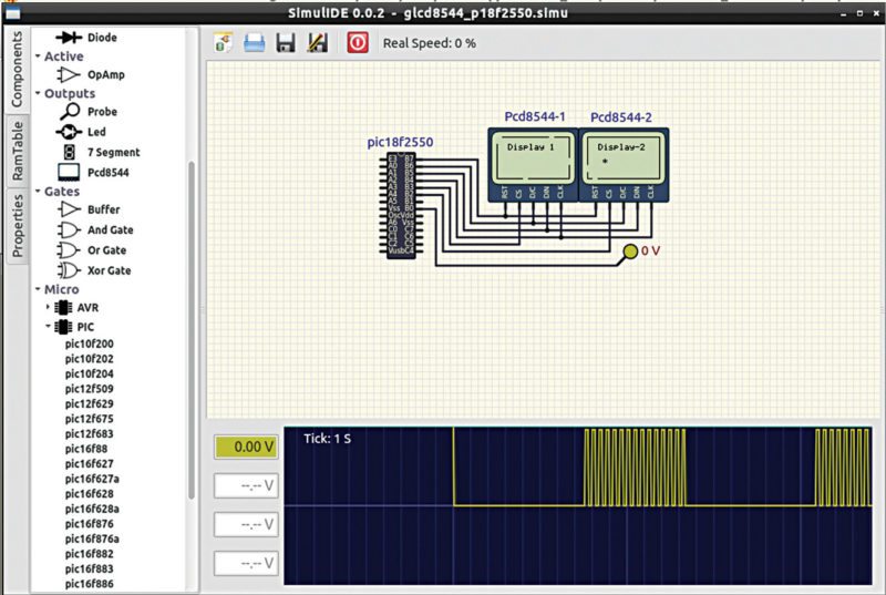
Simple circuits are not just about putting together resistors, capacitors and inductors, of course. You often need a controlling section or an integrated circuit (IC). To aid easy development of such systems, SimulIDE provides support for simulation using microcontrollers.

SimulIDE provides AVR, Arduino and PIC microcontrollers that can be accessed just like other components. Features like gpsim and simavr allow you to use PIC and AVR microcontrollers, respectively. Make sure these add-ons are installed on your system, too. You can load and reload firmware as many times as you want, and watch the movement of data between registers on the screen. The kit also comes with a serial terminal that you can pair with your board.
Design with ease
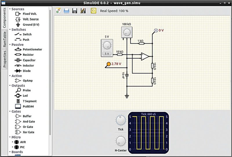
On getting into the application, a window opens up with a huge space for the actual design. An all-powerful, right-click accessible context menu lets you select components and place these in the angle you want. You can even save the circuit as an image file at any instant easily from the same menu.
A column on the left-most corner shows three tabs. On opening any of these tabs; a column opens up between this and the design window. This acts as the user interface for the intricacies of the circuit. Take a look at the three available categories.
Components.
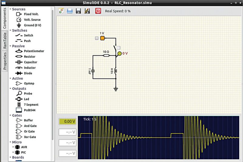
The components section lists out all available components for you to choose from. You just have to drag and drop each component and connect these together by wires, which are automatically laid out when you draw a line with the mouse. Components are grouped together like voltage, current, clock and ground; switch category that provides a switch or a push button; passive components like resistors, diodes, capacitors, inductors and potentiometer; and active components like op-amps.
You can connect probes, LEDs, etc and view the output of your circuit according to your requirement. Buffers and logic gates like AND, OR and XOR are available to connect anywhere in the circuit. The readily-available AVR or Arduino microcontrollers or 74HC series ICs also need no prior setup, and can simply be added and connected directly in the circuit.
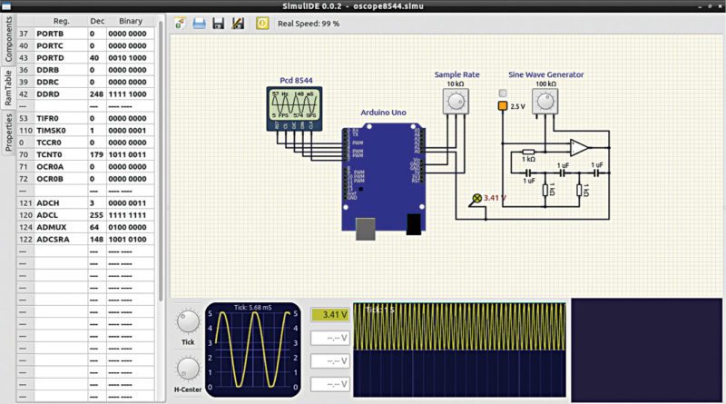
RAM table.
This section comes in handy while working with microcontrollers. Once the firmware is loaded in, you can observe this section to observe data flow between internal registers. As shown in Fig. 4, you can see that RAM Table window displays the details of the various registers along with their location addresses, designated names and current values in decimal and binary number systems.
Properties.
Coming to actually creating your circuit, properties of every component can be viewed, set or modified easily. On clicking on a component, all its related parameters can be edited from Properties window.
For reactive components, the step length can be varied by changing ReactStep value. The longer this value, the faster the element will simulate; but keep in mind that accuracy is compromised. If the reactive component is used in a high-frequency circuit, be aware of the period length while handling this value. In general, circuit simulation speed is measured in steps per second.
Getting down to actual simulation
Simulating with SimulIDE is easy—a power button is your control key. Simply click on it and you will see the circuit getting into action. Observe the outputs you defined to learn how the changes you made to the schematic resulted in new results.On installing SimulIDE package, an exclusive folder is created. This should be used as your workspace for all further designs with this tool. The folder also contains an exclusive folder, for example, where files for designs like op-amp, DACs and so on are provided. Just import the files into the tool and you will see the simulation for yourself.
Being a hobbyist-oriented tool, users of SimulIDE have developed many games like the once-popular Snake and Flappy Bird, samples of which are also provided along with other examples. May be you could try your hand at some new fun game.

Software seems to be a good add on to any Lab, unfortunately it adds maliciuos extension in your PC. Not recommended.
I would like to add the NE555 chip. Can anyone tell me how to do it.