

QUCS is a circuit simulator with well-advanced graphical user interface (GUI) which allows setting up of schematics and presenting simulation results in various types of diagrams. Here is an overview of how to start working with it
Pankaj V.
If you have been looking for an easy-to-use circuit simulator with a graphical user interface (GUI), QUCS is the answer. Its well-advanced GUI allows setting up of schematics and presenting simulation results in various types of diagrams. It supports all kinds of circuit simulation, such as DC, AC, S-parameter, transient, noise and harmonic balance analysis along with the availability of mathematical equations and use of a sub-circuit hierarchy (with parametrised sub-circuits). It also supports pure digital simulations using VHDL and/or Verilog, and you can also import existing SPICE models for use in your simulations.
The latest release comes with an interactive GNU/Octave interface. This new version supports pre-compiled VHDL modules and libraries made from user-written VHDL code, C++ code export of symbol drawings associated with Verilog-A files and direct association of symbol drawings to Verilog-HDL, Verilog-A and VHDL code. You can use sub-circuits equations in Verilog-HDL and VHDL and highlight the syntax for Octave, Verilog-HDL and Verilog-A syntax in text documents. Besides, several new components, such as transistor models NIGBT, HICUM L2 v2.24, HICUM L0 v1.2g and HICUM L0 v1.3, tunnel diode, ideal coupled transmission line and an ideal hybrid are included. And now, the equation solver has an EMI receiver functionality implemented.
System requirements
QUCS code is written in C++ and the software can be run on multiple platforms, viz, Windows, Linux and MacOSx.

Tool suite
QUCS consists of various standalone tools which interact through GUI. The GUI is used to create schematics, set up simulations, display simulation results, write VHDL code, etc; the backend analog simulator a command line program to simulate the schematics; a simple text editor edits the files included by certain components (SPICE netlists or Touchstone files) and displays netlists and simulation logging information; a filter synthesis application, helps design various types of filters; a transmission line calculator help design and analyse different types of transmission lines (microstrips, coaxial cables); a component library holds models for real-life devices (transistors, diodes, bridges, op-amps, etc); attenuator synthesis application helps design various types of passive attenuators; a command line conversion program imports and exports datasets, netlists and schematics from and to other CAD/EDA software.
Getting started
Run the setup file qucs-0.0.17.exe and install the software following all the procedures. The setup will give you an option to install other bundled software, namely, iverilog 0.9.6, Mingw32 0.0.2 which is required for Free HDL, Free HDL 0.0.8 and a download option for Octave. After installing the package, you can launch the program.
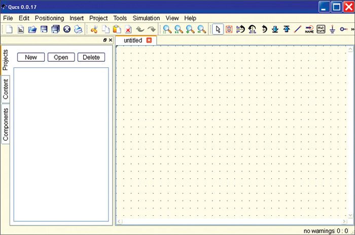
The main window would appear as shown in Fig. 1. When you open QUCS for the first time, Projects tab on the left hand side will be empty; otherwise, it will display a list of all the projects. Schematic area is on the right hand side; different menu bars and toolbars can be seen on the top of this window.
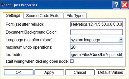
Since you are opening QUCS for the first time, you can configure the language and appearance settings in the File→Application Settings menu. It will open the QUCS property editor (Fig. 2) where you can make the desired changes. For the changes to take effect, application must be closed and reopened via File→Exit menu or ctrl + Q shortcut.
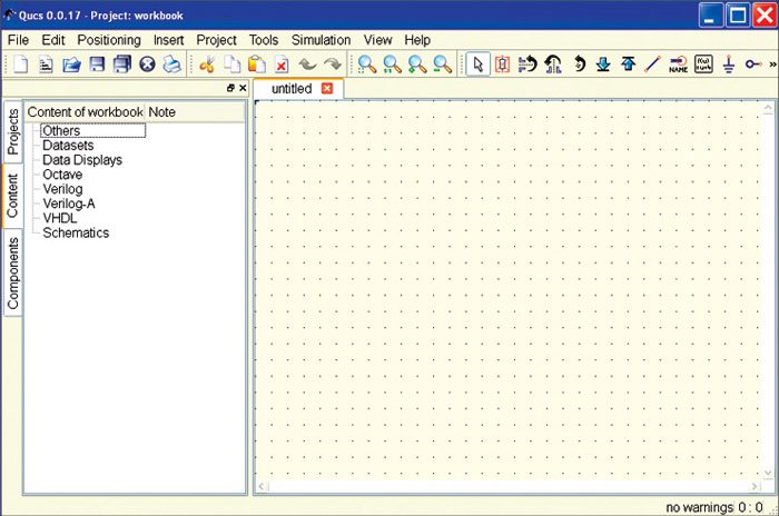
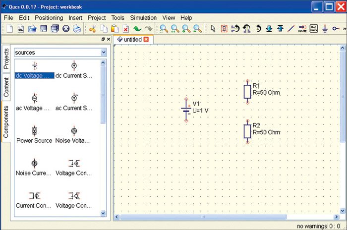
Create new schematic
For setting up schematics, let us create a new project. Either press the New button above the projects folder or use the menu entry Project→New Project and enter the new project name. After creating the new project, QUCS shifts to Content tab where you can find all the data related to the project, i.e. your schematics, the VHDL files, data display pages, datasets as well as any other data (such as datasheets). Right hand side is the untitled empty schematic (Fig. 3).


