

Being a free electronic circuit simulator, this is an efficient tool for an electronics engineer to simulate analogue and digital systems as well as analyse their system behaviour.
Jai Sachith Paul
Circuit simulation is a critical step in electronic product design. By simulation a design, an engineer will know the behaviour of the circuit on various test cases even before practically implementing it. Getting the design right at the first implementation saves a lot of time and cost for the manufacturer. This, in turn, helps the manufacturer to reduce the time to market.
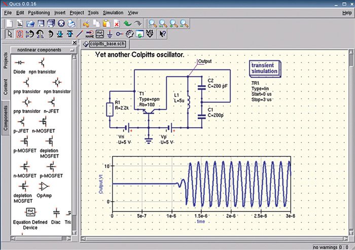
 Quite universal circuit simulator (Qucs) is a free open source integrated circuit simulator with a smart graphical user interface (GUI). The GUI in Qucs is based on Qt, which is a cross-platform application framework. We can run AC, DC and transient analysis, in addition to VHDL/Verilog simulations, very easily with the help of this circuit simulator. Apart from this, we can easily import any existing SPICE model for our circuit simulation.
Features of Qucs
Let us take a look at the main features of Qucs:
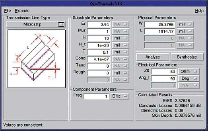
Massive component library. Qucs comes up with almost all the components required for an electronic circuit. The library consists of lumped elements like resistors, inductors and capacitors as well as models for sources, probes and transmission lines for electronic circuits.

We can also find non-linear components like diodes and transistors in the library. It includes various transistor models like heterojunction bipolar transistor (HBT), metal semiconductor field effect transistor (MESFET), metal oxide semiconductor field effect transistor (MOSFET) and junction gate field effect transistor (JFET) in the component library. Additionally, users of this tool are given the provision for expanding the libraries as per their requirements.
Smart GUI. You have access to a very useful GUI in Qucs that is based on Qt by Digia. This helps us create schematics or write VHDL code using the user interface. Setting up simulations and displaying their results is very easy using this GUI.
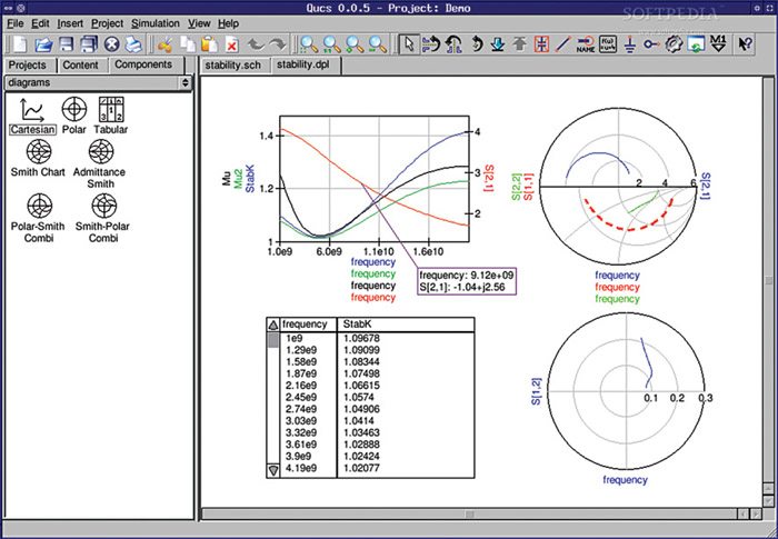
The GUI aids in efficient schematic capture by allowing the simulated data to be represented in various forms as Smith chart, tabular, cartesian, polar, Smith-polar combination, 3D-cartesian, locus curve, timing diagram and truth table.
Analysis of results made easy. Various types of analyses are possible with the help of Qucs. We can get the small signal response of a circuit using AC analysis, while the DC sweep analysis in Qucs could be used to calculate the circuit’s bias point over a range of values. The transient analysis helps us compute the response of the circuit with respect to time.
Not only can we easily calculate the contribution of noise from the resistor and semiconductor devices in the circuit with the help of noise analysis, we can also vary the range of values of a component in the circuit and note the response using Qucs with the help of parameter sweep analysis. It is easy to obtain scattering parameters by using S parameter simulation in Qucs, while pure digital simulations are supported by VHDL and Verilog HDL in Qucs.
What users think about this tool
The strength of any tool lies in the experience that it can provide its users. Going through the reviews in the online communities, we realised that users are quite impressed with this product.
A user from sourceforge.net writes, “This is a very nice product. I am a DSP guy, so I do not use circuit simulators often. I have some experience with SPICE and Orchad, but I have a very strong preference for Qucs. It is easier to use and richer in features. For example, the basic OpAmp is just what you need when you want to make some examples in class without drowning in the complexities of a real OpAmp.”
Another user from apps.ubuntu.com says, “I have only played with this briefly, but if you are familiar with Agilent Design System (ADS), then you will pretty much be right at home. That being said, if you are not familiar with ADS, then it could be a bit confusing. Features included are: AC, DC, harmonic balance, S parameter sims, Smith charts, as well as cartesian plots for transient sims, SPICE models for transistors and FETs, and file based circuit elements. It looks like it will be adequate for hobby circuit building. In fact, it is probably the most complete open source circuit simulator that I have found.”
Why not give it a try
Qucs is already a very popular electronic circuit simulator among design engineers. It is free and an open source simulator. If you are a designer or student who is curious to know how a circuit works, you must give it a try today itself.
Download latest version of the software: click here
The author works at EFY
