

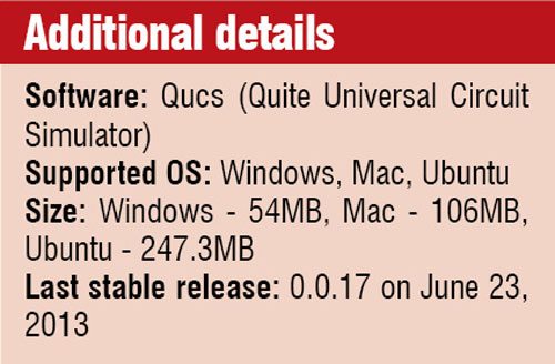
In this article we explore the features and functions of Quite Universal Circuit Simulator (Qucs) and go through a step-by-step analysis. Qucs is available for Windows, Mac and Ubuntu (open source).
Abhishek A. Mutha
 An open source electronics circuit simulator software released under GPL, Quite Universal Circuit Simulator (Qucs) provides the user with capabilities to set up a circuit with a graphical user interface. It can simulate circuit behaviour, and supports pure digital simulations using VHDL and/or Verilog languages.
Qucs is much simpler to use and handle than other circuit simulators like gEDA or PSpice. It also supports a growing list of analogue and digital components as well as Spice sub-circuits, which makes it easier to work with.
What is Qucs all about
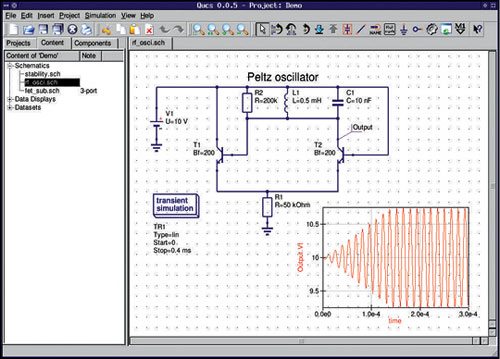
Qucs is an integrated circuit simulator that enables you to set up a circuit with its intuitive graphical user interface (GUI) and simulate the small-signal, large-signal and noise behaviour of the circuit. Post simulation, you can view the simulation results on a presentation page or window.

Qucsator and GUI
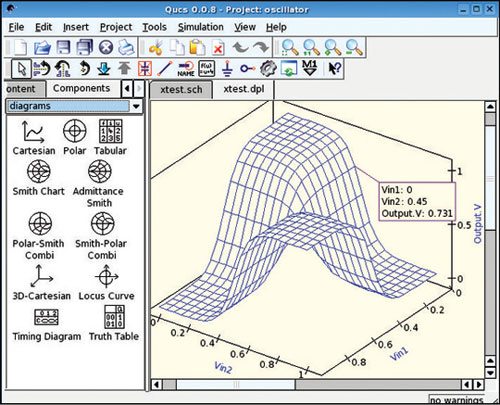
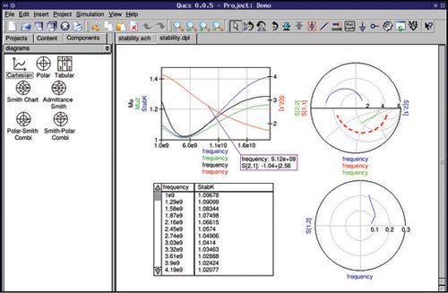
The GUI is based on Qt by Digia. The software aims to support most kinds of circuit simulation like DC, AC, S-parameter, harmonic balance analysis and noise analysis to name a few. The Qucs GUI is well advanced and allows setting up schematics and presenting simulation results in various types of diagrams. Apart from representation in DC, AC, S-parameter, noise and transient analysis, mathematical equations and use of a sub-circuit hierarchy (with parameterised sub-circuits) are also available. Qucs can also import existing Spice models for use in your simulations.
Qucsator, the simulation back-end, is a command-line circuit simulator. It takes a network list in a certain format as input and outputs a Qucs dataset. It has been programmed for usage in the Qucs project but may also be used by other applications.
Qucs comes with a huge array of components and models including HICUM, BSIM2, BSIM3 and BSIM6 to list a few. It also provides semiconductor-based components and models such as PMOSFETs, MOSFETs, op-amps, diodes and many more.
While some examples have been included in this story to demonstrate some of the abilities of Qucs.
Features and their functions
Qucs consists of several stand-alone programs interacting with each other through the GUI, such as:
GUI. It is used to create schematics, set up simulations, display simulation results and to write VHDL code.
Back-end analogue simulator. The analogue simulator is a command line program which is run by the GUI in order to simulate the schematic that you previously setup. It takes a netlist, checks it for errors, performs the required simulation actions and finally produces a dataset.
Simple text editor. This is used to display netlists and simulation logging information, and also to edit files included by certain components (like Spice netlists or Touchstone files).
Filter synthesis application. The program can be used to design various types of filters.
Transmission line calculator. This can be used to design and analyse different types of transmission lines (examples: micro-strips, coaxial cables).
Component library. The component library manager holds models for real-life devices, such as transistors, diodes, bridges and op-amps. The user can extend it with additional components.
Attenuator synthesis application. The program can be used to design various types of passive attenuators.
 Command line conversion program. The conversion tool is used by the GUI to import and export datasets, netlists and schematics from and to other CAD/EDA software. The supported file formats as well as usage information can be found on the home page of Qucs.
Additionally, the GUI steers other EDA tools. For digital simulations (via VHDL) the program FreeHDL (see http://www.freehdl.seul.org) is used. And for circuit optimisations ASCO (see http://asco.sourceforge.net) is configured and run.
Getting started
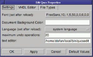
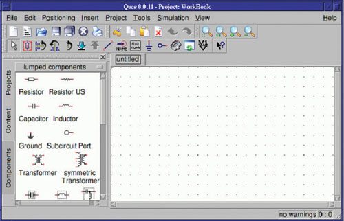
Once the software has been successfully installed on your system you can start it by issuing the # qucs command, or by clicking the appropriate icon on your start menu or desktop. Qucs is a multi-lingual program. Therefore, depending on your system’s language settings, the Qucs GUI appears in different languages.
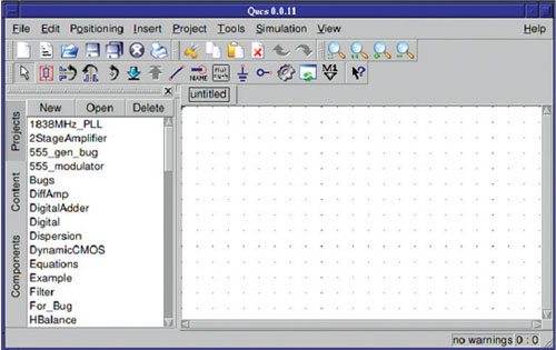
On the left hand side you will find the Projects folder opened, as shown in Fig. 1. Usually, the projects folder will be empty if you are using Qucs for the first time. The large area on the right hand side is the schematic area. Right above it you can find the menu bar and the toolbars. Go to File → Application Settings menu to configure the language and appearance of Qucs.


