

Field engineers can work in a variety of jobs. They are specialists employed at companies that offer services to clients, and usually work in the field, i.e., locations owned by the client and not by the company at which they are employed. The locations can range from various production facilities and plants to oil fields. In the field, they can act as service representatives, oversee operations, install equipment and maintain and repair the existing equipment or supervise all engineering operations.
A lot of times in India, we see field engineers with strange tools such as a bulb holder connected to two wires for testing the continuity. These tools may do the job but are not safe and accurate. So here we present some basic tools for field engineers and discuss why and how they are used.

Clamp meter
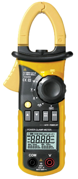
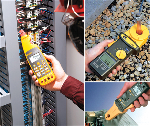
Flow of electrical charge (current) is used to power everything from appliances at home to huge machinery at various industries. In cases where electricity-powered equipment need to be repaired, serviced, maintained or installed, clamp meters can be indispensable tools. A clamp meter is a device that measures various properties of an electrical current. It is a preferable device in the field due to its numerous advantages, including safety, efficiency, versatility and convenience. When clamp meters are used, you do not need to cut any wires, lowering the chances of fatal shocks. Clamp meters can give accurate readings, allowing engineers to quickly diagnose and resolve most problems. Fig. 1 shows a clamp meter.
A clamp meter measures current, voltage, crest factor and continuity. AC current is the primary measurement that a clamp meter should be able to perform. These measurements are taken from different branches of a distributed system to debug the issue.
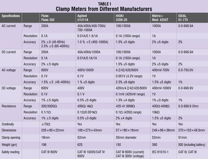
If an appliance is not working, the first thing to check is the input supply. Most clamp meters are capable of reading AC and DC voltages. These meters can also read crest factor which refers to the measurement of a waveform. The crest factor value is determined by the waveform’s peak value versus its RMS value and is important in determining whether a circuit is overloaded. Continuity can also be checked using a clamp meter and the same is indicated with a beeprs. Table I shows various clamp meters available from different manufacturers.
Insulation resistance tester

Eighty per cent of electrical maintenance and testing involves evaluating insulation integrity. Harsh installation environments, especially those with extreme temperatures and/or chemical contamination, cause deterioration to the insulations and, as a result, personnel safety and power reliability can suffer. So it is important to identify this deterioration as quickly as possible so you can take the necessary corrective measures. Fig. 2 shows an insulation resistance meter.
To test the insulation, we apply a highly regulated, stabilised DC voltage across a dielectric and measure the amount of current flowing through that dielectric, and then calculate the insulation resistance using Ohm’s law. The current here is the leakage current and the resistance is in mega ohms. This value of resistance is used to evaluate the integrity of the conductor.
Generally, positive and negative leads are put across an insulation barrier. A third lead, which connects to a guard terminal, may or may not be available with every tester. After the connections are made, test voltage is applied for a minute, which is a standard industry parameter that allows you to make relatively accurate comparisons of readings from past tests done by other technicians. During this interval, the resistance reading should drop or remain relatively steady.
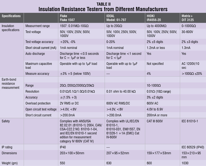
Larger insulation systems will show a steady decrease, whereas smaller systems will remain steady because the capacitive and absorption currents drop to zero faster than on larger systems. After one minute, you should read and record the resistance value. Table II shows insulation resistance testers from different manufacturers.
Earth ground tester
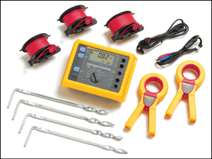
A proper grounding system is of huge importance in the industrial and home environment. Proper grounding of metallic enclosures and support structures that are part of the electrical system helps avoid fatal shocks due to any kind of electrical system failure. The grounding system also provides protection against static electricity from tribocharging. Another important use of grounding system is protection against direct lightning strokes.
It is estimated that at least 15 per cent of the power quality problems are related to improper grounding. Therefore good grounding ensures that these problems do not escalate. Fig. 3 shows an earth ground tester and table III shows the testers from different manufacturers.


