


 Solar powered lighting systems are now used in rural as well as urban areas. These systems include solar lanterns, solar home lighting systems, solar streetlights, solar garden lights, solar water heaters and solar power packs. All of them consist of four components: solar photovoltaic (PV) module, rechargeable battery, solar charge controller and load. The solar charge controller plays an important role as the system’s overall success depends mainly on it. It is considered as an indispensable link between the solar panel, battery and load.
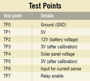
Here we present the circuit of a PIC microcontroller based solar charger that is highly efficient. This automatic solar charger is built around a PIC16F877A microcontroller. It shows the system status on an LCD and can trickle charge.
Circuit and working
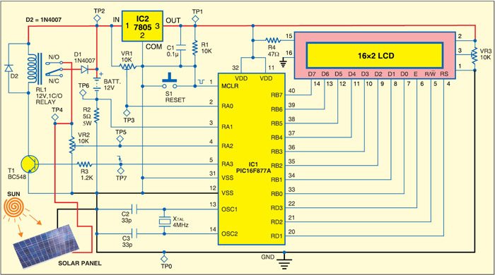
Fig. 1 shows the circuit of a PIC microcontroller based solar charger. In addition to microcontroller PIC16F877A (IC1), it uses regulator 7805 (IC2) and a few discrete components.

PIC16F877A is a powerful microcontroller that provides an ideal solution for hobby and industrial development. It controls battery charging through the solar panel. PIC microcontrollers use Harvard architecture.
 PIC16F877A is an 8-bit, high-performance RISC CPU with low power consumption. It has 8kB flash, 256 bytes of EEPROM, 368 bytes of RAM, 33 input/output (I/O) pins, 10-bit 8-channel analogue-to-digital converter (ADC), three timers, watchdog timer with its own on-chip R-C oscillator for reliable operation and synchronous I2C interface. The microcontroller can recognise and execute only 35 simple instructions. All the instructions are single-cycle, except branches which are two-cycle instructions.

Port pins RB0 through RB7 of the microcontroller are connected to data pins D0 through D7 of the LCD module, respectively. Port pins RD1, RD2 and RD3 are connected to RS (register-select), R/W (read/write) and E (enable) of the LCD, respectively. Preset VR3 is used for contrast control. Switch S1 is used for manual reset. A 4MHz crystal along with two 33pF capacitors provides basic clock frequency to the microcontroller.
Port pins RA0, RA1 and RA2 receive inputs to monitor battery voltage, charge current and solar panel voltage, respectively, to control the overall process and display information on the LCD module. When port pin RA3 goes high, transistor T1 becomes saturated and relay RL1 energises to connect the solar panel to the battery.
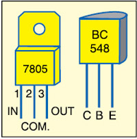
Regulator 7805 provides regulated 5V to the microcontroller and the LCD module. Fig. 2 shows the pin details of regulator 7805 and transistor BC548.
This solar charger can charge the battery in two modes—boost and trickle. If battery voltage is greater than 12V the battery is charged in trickle mode, whereas if battery voltage is less than 12V it is charged in boost mode. In trickle mode, the battery is charged at discharge rate.
The system also calculates the energy that has been received from the solar panel. This gives an indication of the power that can be harnessed from the Sun.
Construction and testing
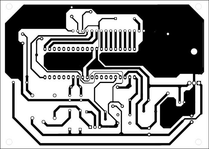
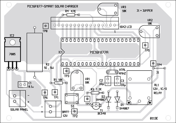
A single side PCB for the PIC microcontroller based solar charger is shown in Fig. 3 and its component layout in Fig. 4. Assemble the circuit on a PCB to minimise time and assembly errors. Carefully assemble the components and double-check for any overlooked error. Use IC base for microcontroller PIC16F877A. Before inserting the IC, check the supply voltage (5V) at test point TP1.
Before using the circuit, the system has to be calibrated for battery and solar voltages. This is done as follows:
Battery voltage
With battery disconnected, apply 20V at TP2 with respect to TP0. Use a multimeter to monitor the voltage at test point TP3 and adjust preset VR1 to get 5V. Check whether the voltage at TP6 is around 5V. Connect back the batteries. Now the voltage at TP3 should be around 3V.
Solar voltage
Remove the solar panel from the circuit. Connect a 12V battery at test point TP4 with respect to TP0 and monitor the voltage at test point TP5. Adjust preset VR2 to get 3V. Relay (RL1) enable can be checked at TP7.
The circuit is ready to harness the energy of the sun after calibrations. The power is calculated and displayed on the LCD in watts every second. The energy in watt-second is calculated by integrating the power.
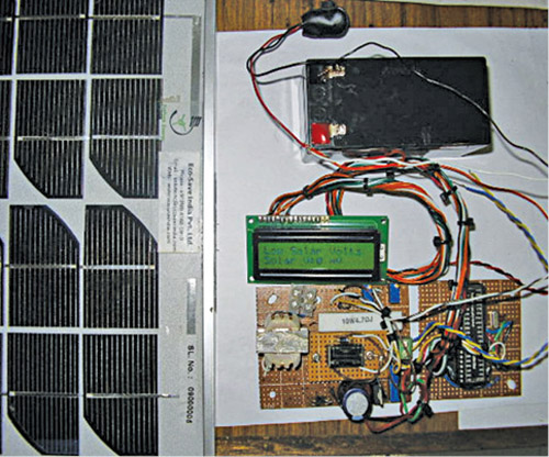
Fig. 5 shows the working prototype of PIC16F877-based solar charger.
The following parameters are cyclically displayed on the LCD module:
1. Battery voltage in millivolts
2. Battery current in milliamperes
3. Energy in watt-seconds
4. Power in watts
5. Solar panel voltage in millivolts
6. Charger mode: boost or trickle
Download PCB and Component layout: click here
Download Source Code: click here
Software
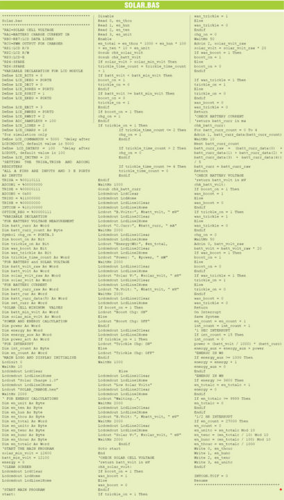
The source program is written in basic language and compiled using PIC Simulator IDE from Oshonsoft. The IDE provides a facility to program using Basic like commands, then compile the program and generate hex code. Burn the generated hex code into the microcontroller by using a suitable programmer.
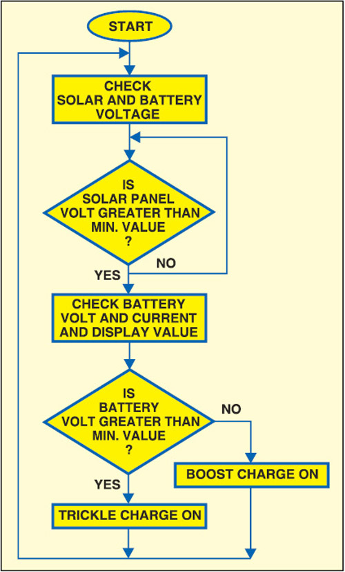
The program works as per the flow-chart shown in Fig. 6. It starts by checking solar panel voltage. If solar panel voltage is more than 12.6 volts, the program moves to the next stage. If solar panel voltage is less than 12.6 volts, the program displays message “Low Solar Volts” on the LCD module and loops back to wait until solar panel voltage is above 12.6 volts.
If solar panel voltage is adequate, the system checks battery voltage and sets the charging mode to ‘boost’ or ‘trickle.’ A battery voltage of over 12V sets charging mode to ‘trickle,’ while a battery voltage of less than 12V sets it to ‘boost’ mode. During initialisation, the data is also read from the EEPROM, which stores the watt-hour readings. It gives an indication of the power absorbed from the sun.
The timer generates an interrupt every 65.56 ms. A 15-count in the interrupt service routine ensures that the energy and power are calculated every 65.56×15 =983.4 ms (almost 1 second).The power is integrated every second to get the energy in watt-seconds. The watt-hour readings are stored in the EEPROM of the microcontroller, so that the data is not lost due to power failure. To prevent too many write cycles in the EEPROM, the data is stored only every 30 minutes.
The author is working at Tata Realty and Infrastructure in Engineering Services as AGM


EFY u do nice project.i build this project work fine.ThnQ EFY
You are most welcome.
do you have program using C?
Btw, hw many watt solar panel that you use in this project?
do you have the same project on simulink??
sir do this cod will run in MPLAb
i tried to run the asm, file it couldnt run
please, anyone help me
thank u
hie sir do have the hex file of the this project. pliz help.
thank u
i have just one qestion if an panel 50w with max 2.5amps is no strong for d1….i think the diode is just for 1 amp and if i use another tip ex…6 amp ultra rectifier diode and the relay change with another contact ex auto tip will damage ? just right now i built this and im not sure i intent to use 100w panel…..thank yo
is working
a litle error but is fine
Could you please let us know what the error was?
How many watts and volts should be the solar?
can we use a 12v solar panel with 20 watt?
I want to buy this project.Also I did not find the pcb and source code on the web page.
Please reply.I am very keen and most urgent.
You can contact me on 9428974160 or 9586371277.
I made this pcba and tried to use but the realy keeps on switching on off. The RA3 pin suddenly looses its voltage even in boost mode and same happenes in trickle mode too. Please look into the problem regards