Strobe lights are widely used by disco lovers to create wonderful visual effects in disco halls and auditoria. The circuit of a battery operated portable miniature strobe light, which can be constructed using readily available inexpensive components, is described here.
For convenience and simplicity, an ordinary neon lamp is used here in place of the conventional Xenon tube. The whole gadget can thus be easily accommodated in a small cabinet, such as a mains adapter cover, with a suitable reflector for neon lamp to give a proper look. Since current requirement of this circuit is very small, it may be powered by two medium-size dry cells (3V) or Ni-Cd cells (2.4V).
Miniature strobe light circuit
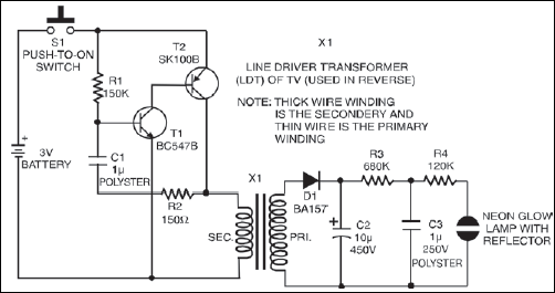
Transistors T1 and T2 in the circuit form a complimentary-pair amplifier. When switch S1 is momentarily depressed, the circuit oscillates because of the positive feedback provided via resistor R2 and capacitor C1 to the base of transistor T1. The sharp pulses in the secondary windings induce a high voltage in primary windings of transformer X1, which in fact is a line driver transformer (used in reverse) generally used in 36cm TV sets.

High voltage pulses induced in primary side are rectified by diode D1 and rapidly charge reservoir capacitor C2 to nearly 300V DC. When switch S1 is released, capacitor C2 holds the voltage level for a finite period while capacitor C3 charges slowly through resistor R3. As voltage across capacitor C3 becomes high enough, neon strikes and the capacitor rapidly discharges through the lamp. When voltage across capacitor C3 falls below the extinguishing potential of neon lamp, it goes off and capacitor C3 starts charging again. This cycle keeps on repeating for a short time, based on the reservoir capacitor C2’s value.
Precautions
The neon lamp flasher section of this circuit carries dangerously high voltages. All precautions should therefore be taken for protection. Before any repair work, discharge capacitor C2 using a short length of wire with a 100k resistor connected in series.
The article was first published in January 2007 and has recently been updated.


