
 Testing of digital electronic systems generally involves applying a set of test stimuli to inputs of the device-under-test (DUT) and analyzing responses of the system using a response analyzer. If the DUT generates correct output responses (also called the golden response) for all the input stimuli, the DUT is regarded as fault-free. Those DUTs that fail to meet the golden response are regarded as faulty or defective. This project describes a digital IC tester for testing 74xx series digital ICs using a MATLAB graphical user interface (GUI) drop-down menu based approach. Block diagram for testing a device is shown in Fig. 1.
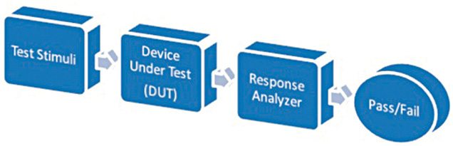
MATLAB acts as the test stimuli generator to the IC, which is the DUT. The GUI initiates communication with the Arduino and provides a user-friendly and interactive approach to conduct the test. The MATLAB source program (ic_tester.m) acts as the response analyzer and displays test results on the front panel of the GUI.
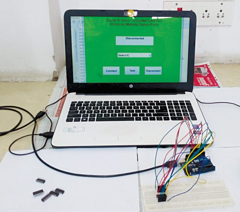
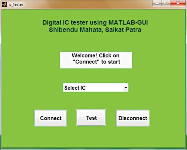
Authors’ prototype of the Arduino based digital IC tester and the MATLAB based GUI front panel are shown in Figs 2 and 3, respectively.
Digital IC Tester Circuit and Working
Circuit diagram of the Arduino based digital IC tester is shown in Fig. 4.
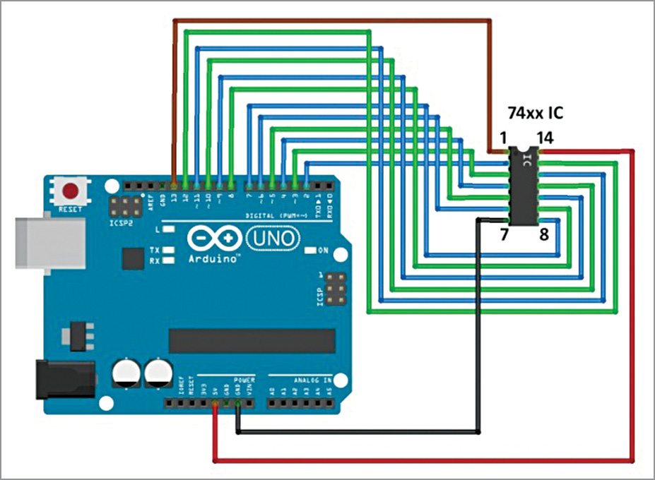
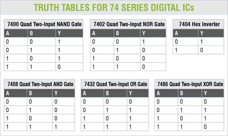
As mentioned earlier, MATLAB is used to apply stimuli to the DUT (74xx series digital ICs) and also record the response of the DUT to stimuli. It then compares the response of the DUT with the correct/golden response to test whether the device is faulty or not. For a digital IC, the correct response is given in the form of a truth table. Acting as a response analyzer, the MATLAB verifies each and every possible outcome according to the truth table of a particular IC.

74xx series ICs that can be tested by this project are 7400, 7402, 7404, 7408, 7432 and 7486. Truth tables for these ICs are shown on the next page.
Software
1. Arduino IDE 1.6.5 is used to program the Arduino. The GUI application program has been developed in the R2014a version of MATLAB. The procedure to install the ‘Legacy MATLAB and Simulink Support for Arduino Package’ is described in ‘Controlling a Robotic Car Through MATLAB GUI’ DIY article.

2. After correctly setting up the path for the package, open source code files (ic_tester.m) of this project. Keep both the source code files in the same folder. Edit COM port (in the line a=arduino (‘COM19’)) with the port number in your PC where the Arduino Uno board has been installed. Run the file and click ‘Connect’ button to establish connection between MATLAB and Arduino Uno board. After successful communication is established, select proper IC from the drop-down menu and click ‘Test’ button in the GUI to test the IC.
Download source code
Saikat Patra is passionate about electronics and MCU-based embedded system applications.
Shibendu Mahata is an M.Tech (gold medallist) in instrumentation and electronics engineering from Jadavpur University. Currently, he is pursuing Ph.D from NIT, Durgapur. He has keen interest in MCU-based real-time embedded signal processing and process control systems


Can I also include
the ic testing series like 4××× series
The author Shibendu replies:
Our program will work only for the 74xx series. Since the 4xxx
series has different input-output pin configuration, hence, you have
to modify the program by configuring the i/o pins of Arduino as per
the pin configuration of the 4xxx series. Similarly, the test circuit
also needs to be changed accordingly.
code please
Hi, the source code is present in the article itself.
Its not opening,will u please mail the code and making video to me?Urgent!
Hi Kaushik,
Previously we were facing some technical issue, you can download the source code now.
Its .RAR file how can we convert it in to normal pdf file or text file?Reply As soon as possible because iam doing this as my project.
Hi, there are software likes WINRAR available free on the internet. Just install and extract the PDF, please.
Hi, there are software likes WINRAR available free on the internet. Just install and extract the PDF, please.
CAN I USE MATLAB 2012 VERSION??
Yes u can
where i can find the arduino code??
The source code is present at the end of the article.
We have not tried in MATLAB 2012 version
sir i need full base/Project paper of this project.Can i get it
We do not have other detail/material apart from the article given here.
sir
need to see video of this project
For video, please send your request to [email protected]
Sir, R u provide full material details about this project or video…
Hi Ashfaq all the informtion is provided in the article. Please reply, if you need any specific information about the project.
Hello Sir,
The code required for Arduino is not given.
Can you please share Arduino code?
Thanks and Regards,
A. D. Kale
do u got the arduino code??
hello , i used all the information and all the circuit is right but when i click connect it give me error , can you reply me very urgently please
i can’t open the coding
Kindly refresh the page and retry.
Dot indexing is not supported for variables of this type.
Error in ic_tester_new>popupmenu1_CreateFcn (line 110)
set(handles.text2, ‘String’, ‘Please select an option from the dropdown’);
Error in gui_mainfcn (line 95)
feval(varargin{:});
Error in ic_tester_new (line 41)
gui_mainfcn(gui_State, varargin{:});
Error in matlab.graphics.internal.figfile.FigFile/read>@(hObject,eventdata)ic_tester_new(‘popupmenu1_CreateFcn’,hObject,eventdata,guidata(hObject))
im getting these errors after running the code