
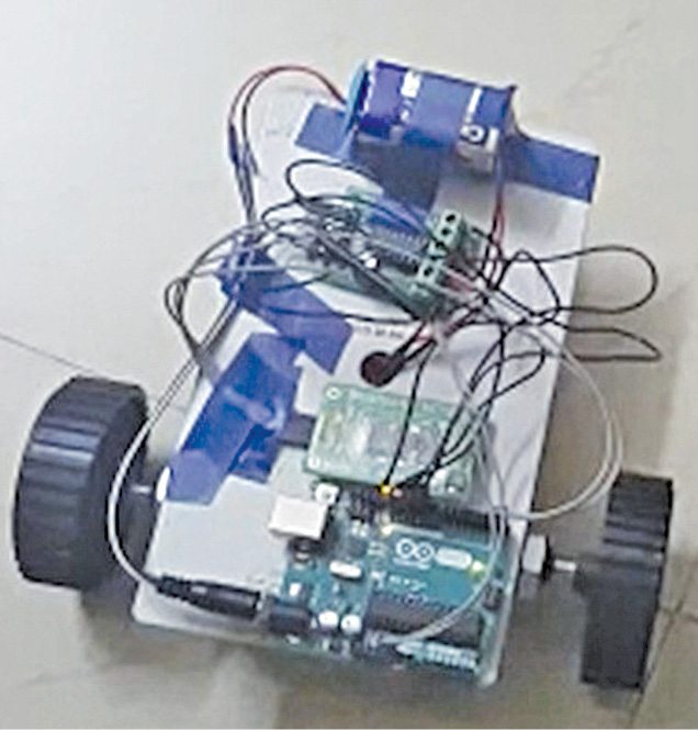
 Nowadays smartphones can be used to control a host of electrical and electronic devices including motors, music systems and lights. Here we present an Arduino based robot car, which can be controlled using an Android smartphone having ArduinoRC application installed in it. This bot receives commands from your smartphone with the help of a Bluetooth module. The authors’ prototype is shown in Fig. 1.
Arduino based robot car circuit and working
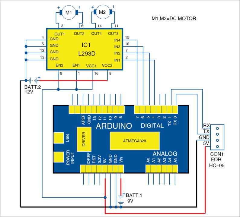
The circuit diagram of smartphone controlled Arduino based robot car is shown in Fig. 2. Pin mapping of the Arduino Uno is shown in Fig. 3.
The ATmega328 chip on the Arduino Uno board comes with a bootloader, which allows you to burn the program to the chip without an external hardware programmer. After the chip is programmed, it can be removed from the board. The board can be powered from USB connection or external power supply such as batteries or AC/DC adaptors. After connecting the power supply to Vin pin, you get regulated 5V and 3.3V DC on the respective pins of the Arduino board. 5V is used to power the HC-05 Bluetooth module.
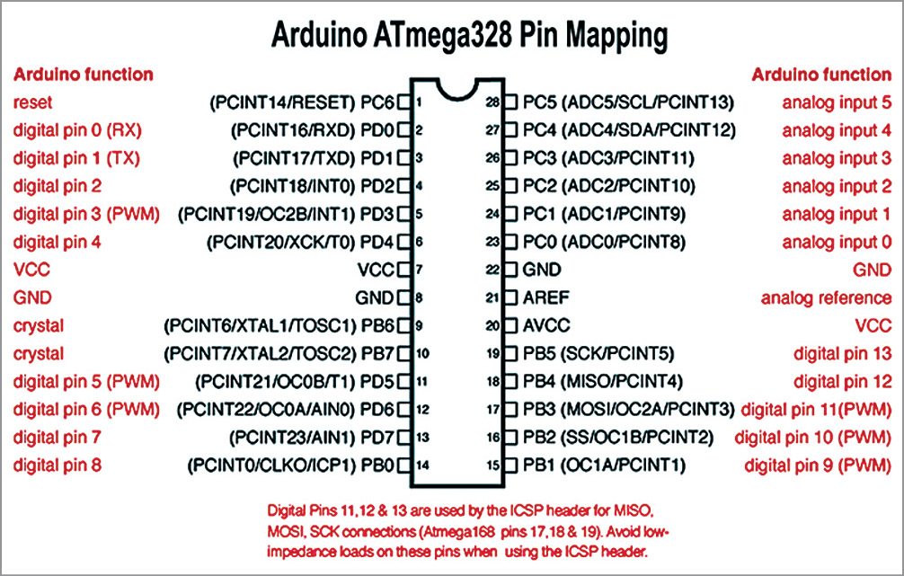
Serial pins 0 (RX) and 1 (TX) of Arduino are used to communicate with HC-05 module. Pins 4 through 7 are connected to H-bridge motor driver L293D IC. Out of these four pins, pins 5 and 6 provide 8-bit PWM output using analogWrite( ) function defined in the asc_car.ino Arduino sketch. Pins 2 and 3 of Arduino (not used in this project) can be used for additional functions like controlling lights, horn, etc.
Construction and testing
A 9V battery supply is used to power the Arduino Uno with its positive terminal connected to Vin pin and negative terminal connected to GND pin. 5V and GND (ground) pins from the Arduino are connected to HC-05 Bluetooth module. RX (pin 0) and TX (pin 1) pins of the Arduino are connected to TX and RX pins of the HC-05 module, respectively.

Pins 4 through 7 of the Arduino provide controlling signals for the motors. The Arduino outputs a very small voltage from these pins. So, an additional power supply is required to produce enough torque for the motors, for which H-Bridge L293D module is used. You can provide additional 12V power supply to pin 8 (VCC2) of L293D to drive the motors.
Output pins 4 through 7 of Arduino are connected to IN1 through IN4 pins of L293D, respectively. Ground pins 4, 5, 12 and 13 of L293D are connected to ground pins of the Arduino. The two 100 RPM geared DC motors (M1 and M2) are directly connected to output terminals of the L293D.
Mechanical arrangement of the bot or car is completed by attaching two wheels to the two motor shafts. Army directional wheels should be used on the front side of the car for moving towards left or right. (Castor wheel was used as the front wheel during testing at EFY Lab.)
The Arduino Uno can be programmed with the Arduino software (IDE). Switch off the Bluetooth module or disconnect it from Arduino while burning the asc_car.ino sketch into the Arduino Uno.

Connect smartphone with HC-05 module. After all the connections and mechanical arrangements are complete, download Arduino Bluetooth Controller app from Google Play Store in Android smartphone. There are many similar apps available on Play Store. This project uses ArduinoRC—an Arduino Bluetooth Controller app developed by Estacado’s Ltd.
Open the ArduinoRC application in Android smartphone and connect with the HC-05 device by typing ‘1234’ or ‘0000’ as pin for pairing with HC-05.
Feeding values in the app.
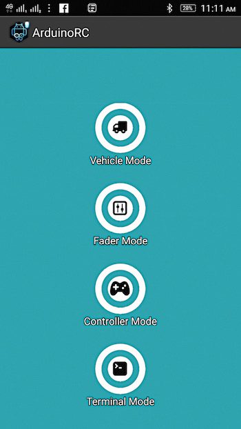
Press ‘Proceed’ option to connect your smartphone with the HC-05 module. You will see a screen on your Android phone as shown in Fig. 4. Select ‘Vehicle’ mode, open the menu in the top-right corner and select ‘Set Commands’ option. Set value ‘4’ for ‘Stop’ button in the application. Similarly, feed values 0, 1, 2 and 3 for Gesture_Front, Gesture_Left, Gesture_Right and Gesture_Back, respectively.
Connect 12V battery supply to L293D module.
Now the bot is ready to be controlled with your smartphone. You can control your bot by tilting the smartphone in different positions. Tilt your phone forward or backward to move the bot in forward or backward direction. Similarly, tilt your phone to the right or left to make the bot take right or left turn, respectively.
With a slight tweak in the circuit, you can also use this app to control lights, horns and music systems by tilting the smartphone in different directions.
Download source code


Very good information of electronics for learning and apply in our life.
Thanks for your feedback.
Can u please send the program for above project.
Hi Harsha, the source code is present at the end of the article.
Can’t download the source code, please help.
Hi, please try to download the Source code in Incognito mode. At my end, I am not finding any difficulty downloading the Source Code.
Sar mujhe a GSM based home automation project main help kariye sir
Kindly elaborate your query.
I just wanted to ask, how much it cost to build this kind of robot?
Hi, the source code is not downloading. I’ve tried to download in incognito mode tooo.
Kindly refresh the page and redownload.
is developer Estacado’s Ltd and Ioannis tzanellis are same