Here is a small digital pulse tester that can be used to test and troubleshoot digital circuitry. The circuit is essentially a pulse generator activated by a single press-to-on switch (pushbutton). Momentarily pressing the pushbutton once generates a single pulse. Keeping the pushbutton pressed produces a train of pulses.
Digital pulse tester circuit
Shown below is the circuit of the digital pulse tester. The frequency and duty cycle of the pulse train can be chosen as desired, as the oscillator is built around the standard astable/monostable chip NE556 (IC1). IC 556 is a dual-timer. The circuit comprises a monostable built around IC1(B), a short-pulse-generating R-C circuit built around gates N1 and N4, capacitor C5 and resistor R9, and an astable multivibrator built around IC1(A).

Circuit operation
Working of the circuit is simple. When you press switch S1 momentarily, it triggers monostable IC1(B), which goes high for about 1.1R3C2 seconds (where R3=4.7 M ohm and C2=47 nF). The output of the monostable is inverted by the short-pulse-generating circuit. LED1 flashes to indicate a single pulse. The single pulse lasts for a short duration as compared to the time period of the monostable IC1(B). Alternatively, you can also see this pulse on an oscilloscope connected between the probe tip and ground. The output of gate N2 is fed to gate N3, which produces the pulse train at the output of gate N4.
Pressing switch S1 enables the astable multivibrator (IC1(A)). Its output remains masked until the output of the monostable (IC1(B)) goes low. When the output of IC1(B) goes low and switch S1 is still kept pressed, the output waveform will be the same as the astable multivibrator’s waveform. It can be seen on the probe tip with the help of the oscilloscope. IC1(A) oscillates only when S1 is pressed. Otherwise, the astable remains in reset state.
In short, the digital pulse tester produces the pulses at the probe tip in the order of single sharp-lapse-train of pulses when switch S1 is pressed.
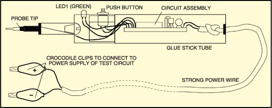
Construction & testing
The entire circuit can be housed in a glue-stick tube as shown in Fig. 2. LED1 is used for pulse indication and incorporated in the probe to make the output visible.
The project was first published in January 2011 and has recently been updated.