
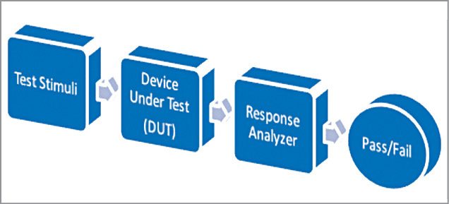
 Testing of digital or analogue electronic systems typically needs application of a set of test stimuli to the inputs of the device under test (DUT) and analysing the output responses using a response analyser. If the DUT generates correct output response (also called the golden response) for all input stimuli, the DUT is regarded as fault-free. Those DUTs that fail to meet the golden response are regarded as faulty or defective. Block diagram for conducting the testing of a DUT is shown in Fig. 1.
In this project, testing of a silicon diode using MATLAB based graphical user interface (GUI) approach is presented. Arduino acts as the test stimuli generator for the diode, which is the DUT. The GUI initiates communication with Arduino and provides a user-friendly and interactive approach for conducting this test. MATLAB source program (diode_test.m) acts as the response analyser and displays the test results on the front panel of the GUI.
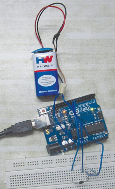
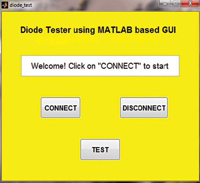
The authors’ prototype of the diode tester and MATLAB based GUI front panel are shown in Figs 2 and 3, respectively.
Circuit and working
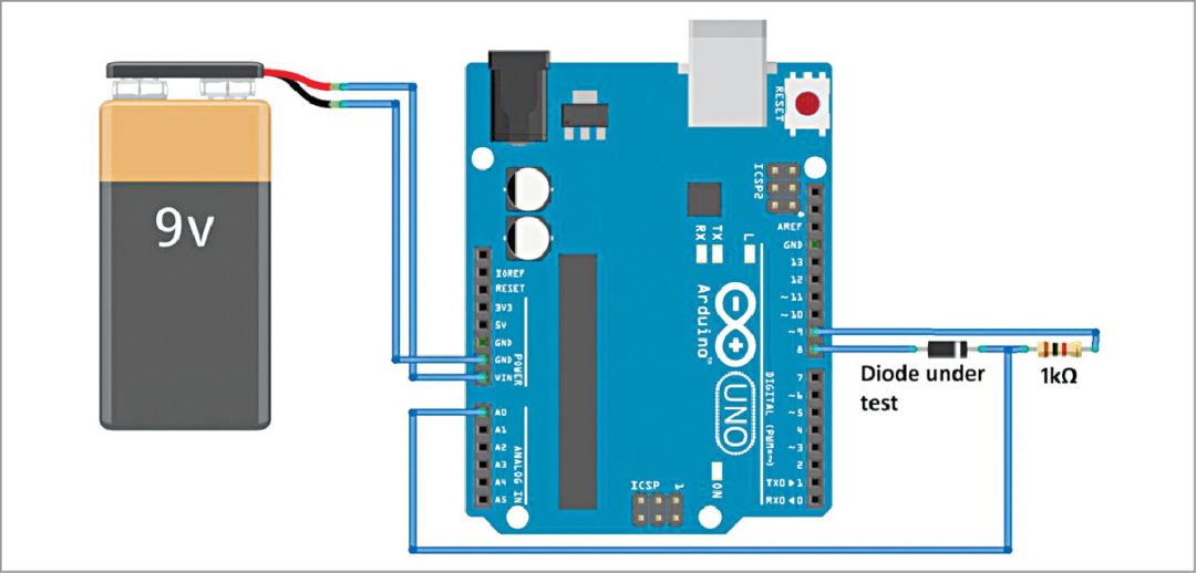
Circuit diagram of the diode tester is shown in Fig. 4. For a good practical silicon p-n junction diode, forward voltage drop is around 0.7V. A p-n junction diode conducts current in only one direction. In forward-biased condition, the diode acts as a very low-resistance path; in reverse-biased condition, it acts as a very high-resistance (ideally infinite) path.
Faults in a diode can be of two types: short circuit or open circuit. In this project, we test whether a diode is in good condition or is faulty. Additionally, the type of fault (open circuit or short circuit) is also displayed on the GUI.
Software
Two different software tools are used in this project: Arduino IDE and MATLAB. Follow the steps given below to install both the software:

We use Arduino IDE for programming Arduino Uno. The latest IDE can be downloaded for free from Arduino’s official website. After downloading Arduino IDE, install it. Note the directory of Arduino IDE installation.
Download Legacy MATLAB and Simulink Support for Arduino package from MathWorks website. Extract the compressed folder named ArduinoIO. From ArduinoIO folder, copy pde folder and paste it in C:\Program Files (or Program files x86)\Arduino\libraries. (The path may be different depending on the installation directory of the IDE.) After pasting pde folder in the correct location, open Arduino IDE. If you have pasted the folder in the correct location, you will find it under File→Examples→pde. Open the code from File→Examples→ pde→adioes.
Connect Arduino Uno board to your PC. From Device Manager, note the COM port at which Arduino Uno board is installed. From Tools menu in Arduino IDE, select the board as Arduino Uno and select the COM port number noted earlier. Upload adioes code to Arduino Uno board by selecting Upload in the IDE.

Copy the entire contents of the extracted ArduinoIO folder to a folder in My Documents (for Windows PC).
Our GUI application program has been developed in R2014a version of MATLAB. After installing this version of MATLAB in your PC, open install_arduino.m file present in ArduinoIO folder. Now run install_arduino.m file. This code will correctly install and save the path of Arduino support package.
Open the source code file for this project titled diode_test.m. Edit the line a=arduino(‘COM19’), substituting 19 with the COM port number in your PC where Arduino Uno board has been installed. Select Connect on the GUI to connect Arduino with MATLAB. After successful connection, connect the diode (in this case, 1N4007) properly, as shown in Fig. 4. Click on Test. If the diode is in good condition, it will display ‘Diode is OK.’ If it is faulty, it will display the type of fault, which is either short-circuited diode or open-circuited diode, on the GUI screen. Click on Disconnect to terminate the test session.
Download source code
Shibendu Mahata is M.Tech (gold medallist) in instrumentation and electronics engineering from Jadavpur University. Currently, he is pursuing Ph.D from NIT, Durgapur. He is interested in MCU based real-time embedded signal processing and process control systems
Saikat Patra is passionate about electronics and MCU based embedded system applications


please send me code for this project
[email protected]
The source code is present within the article.
please can you add or send the code only for arduino software.
Hi Aaron, you can download the Source code from here: http://efymag.com/admin/issuepdf/Diode%20tester%20using%20MATLAB%20GUI.rar
hello. i need the source urgently for a project please. thanks
Hi, you can download the source code from the end of the article.
its not allowing me , could you possibly email it to me or reupload it. will be highly appreciated. thank you sir
Hi, I have sent the source code to your email ID.
please advise me how i can incorporate an ohmmeter with this. thanks in advance