
The other important element of SAW is placed on the glass, which is called reflector. When the panel is touched, a portion of the wave is absorbed. This allows the receiving transducer to locate the touch point and send this data to the system. SAW monitors can be activated by a finger, gloved hand or soft-tip stylus. These monitors offer ease of use and high visibility.
IR matrix based touchscreens. The traditional IR matrix touchscreen technology (Fig. 5) is based on the interruption of a light path in an invisible light grid in front of the screen.
In this concept, an array of emitters (IREDs) is employed and covered behind two adjacent bezels of the screen frame, which creates an invisible optical grid. The opposite bezels contain the respective detector arrays (typically, phototransistors or diodes). If an obstacle (say, a stylus or finger tip) appears inside the grid matrix, it interrupts the light beams and causes a reduction of the measured photocurrent in the corresponding detectors. Based on this information, X and Y coordinates can be easily obtained.
Camera based touchscreens. Recently, there have been developments on camera based touchscreens. This technology is growing in popularity due to its scalability, versatility and affordability, especially for larger units.
The system usually consists of two or more IR line-scanning optical sensors, like the ones used in barcodes or flatbed scanners. Each sensor is mounted on the upper left and right corner of the screen bezel. Sensors monitor the complete screen, which is illuminated with IR light. The IR illumination of the screen area is done by IREDs positioned in upper left and right corners, next to line-scanning sensors but optically isolated to avoid crosstalk. Each of these IRED assemblies illuminates the complete 90° angular range of the screen.

Reflection of a stylus or object (like finger) triggers a rise in the signal of relevant detector cells. By special computational algorithms (for example, triangulation) based on the readout of two line-scanning sensors, exact coordinates and size of the touching object or finger tip can be calculated via software.
Camera based solutions have the advantage of easy scalability. An increase in resolution is commonly achieved by utilising a sensor with higher resolution. Every free space beam tends to broaden over distance. This leads to a decrease in irradiance over distance. The amount of light actually striking the surface of objects in the room is called irradiance level, which depends on the intensity and distance of the light source.
Mathematically, doubling distance r reduces the irradiance by a factor of four. Radiant intensity is related to irradiance as I=E×r2

In some enhanced applications, it might be worth to consider an external lens in front of the emitter to create a slim IR curtain only above the screen. This might also be advantageous in terms of power saving issues, as it allows reduction in IRED drive current.
Haptic sensors
motor (ERM)
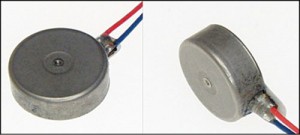
Haptic refers to the sense of touch and is a technology that adds feedback to electronic devices (like tablets and smartphones) through the use of vibration (Fig. 6). The vibration produced by these electronic devices uses two actuators, namely, eccentric rotating mass vibration motors (ERMs) (Fig. 7) and linear resonant motors (LRAs).
In ERMs, vibrations are created in two different perpendicular directions to the rotation axis, while vibrations created by an LRA are based on the movement of a mass that causes repeated displacement in only one direction of axis of linear movement.
ERM has an off-centre load; when it rotates, the centripetal force causes the motor to move. The rotation is created by applying current to armature windings attached to the motor shaft. As these are inside a magnetic field created by permanent magnets on the inside of the motor’s body, a force is created, causing the shaft to rotate. To ensure the rotation continues in the same direction, current in the windings is reversed. This is achieved by using static metal brushes at motor terminals, which connect to a commutator that rotates with the shaft and windings. Different segments of the commutator connect to the brushes during rotation and the current is reversed, maintaining the direction of the rotation.
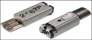
Working of an LRA is similar to how a loudspeaker creates music. In a loudspeaker, the speaker cone is used to produce audio waves through displacement. However, a loudspeaker is designed to operate over a range of frequencies, whereas an LRA is tuned to its resonant frequency. LRAs use magnetic fields and electrical currents to create a force.
One major difference is that the voice coil (equivalent of armature windings) remains stationary and the magnetic mass moves instead. The mass is also attached to a spring, which helps it return to the centre. Driving the magnetic mass up and down causes displacement of the LRA and thereby the vibration force.
Wireless sensors
Wireless sensors are the standard measurement tools equipped with transmitters to convert signals from process-control instruments into radio transmission. The radio signal is interpreted by a receiver, which then converts the wireless signal to a specific desired output, such as analogue current or data analysis via embedded hardware or computer software.
There are mainly four popular wireless sensors, namely, near field communication (NFC), radio frequency identification (RFID), Bluetooth and ZigBee.
Near field communication. NFC is a form of short-range wireless communication where the antenna used is much smaller than the wavelength of the carrier signal and works on either a magnetic field or an electrical field, but does not support electromagnetic fields for wireless communication.
Normally, in mobile phones’ electrical fields, NFC used for short-distance communication operates at 13.56MHz at a wavelength of 22.11m. These are often used in applications like car parking and at ticket counters.
Radio frequency identification. This refers to small electronic devices that consist of a small chip and an antenna. This technology uses small I2C memory chips, enough to track items at a distance.
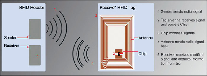
An RF identification system (Fig. 8) uses tags or labels attached to objects to be identified. Two-way radio transmitter-receivers called interrogators or readers send a signal to the tag and read its response. The chip is typically capable of carrying 2000 bytes or less of data.
RFID tags can be passive, active or battery-assisted passive (BAP). An active tag has an onboard battery and periodically transmits its ID signal. A BAP has a small battery onboard and is activated when it is in the presence of an RFID reader. A passive tag is cheaper and smaller because it has no battery.
An RFID device serves the same purpose as a barcode or magnetic strip on the back of a credit card or an ATM card; it provides a unique identifier for that object. And, just as a barcode or magnetic strip must be scanned to get information, the RFID device must be scanned to retrieve identifying information.

Bluetooth. It is a wireless technology standard for exchanging data over limited short distances using short-wavelength UHF radio waves in the ISM band (free band for use in communication) from 2.4GHz to 2.485GHz.
This technology, invented by telecom vendor company Ericsson in 1994, was initially pitched as a wireless alternative to RS232 serial data communication.
Bluetooth (Fig. 9) is managed by Bluetooth Special Interest Group (SIG), which has more than 20,000 member companies in areas of telecommunication, computing, networking and consumer electronics. It was standardised as IEEE 802.15.1 but the standard is not maintaining.
There are two classes of Bluetooth devices; class I has a range of up to 100m and class II a range of up to 10m. In applications like general-purpose wireless communication application, class II is mostly used.
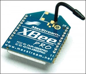
ZigBee (XBee). This is used in high-level communication protocols to create personal area networks built from small, low-power digital radios. ZigBee (Fig. 10) is based on IEEE 802.15.4 standard. Its low power consumption limits transmission distances from 10m to 100m line-of-sight, depending on power output and environmental characteristics.
ZigBee devices can transmit data over long distances by passing data through a mesh network of intermediate devices to reach more distant places. These are typically used in low-data-rate applications that require a long battery life. This type of system is comonly used in home or building automation where more than one node is communicating.


