We all use electronic systems in our day-to-day life. Many times we have seen that when systems fail, things get difficult. Consequences can be serious if failure happens in a critical function. For example, imagine you are travelling in an aircraft and the main controller controlling the aircraft fails. When applications that involve safety of our lives fail, how we handle them becomes critical.
Reliable systems are designed based on the data collected about the failure of the components used in the system. Reliability is a figure that can be predicted based on certain parameters for every system. Essentially, reliability is just a predicted number based on probability and does not let the system work in case of failure.
A fault-tolerant (FT) system, on the other hand, will work even if there is a single or multiple faults (based on design) in the system.
Another critical aspect that we need to remember is how fault-tolerance is implemented. Let us take the example of a telephone exchange. If there is a problem in the phone line or line interface in the exchange, the fault can be rectified only when we replace the faulty part with a good one. However, if the controller controlling the exchange fails, this not only affects the user but also leads to revenue loss as all metering information for on-going calls will be lost. So, most service providers expect exchange controllers, and not the subscriber interface, to be fault-tolerant.

There are certain applications like aircraft controls and nuclear-plant controls that are critical and failure can be life-threatening. For these systems, fault-tolerance will be implemented based on the criticality of the situation. Let us discuss how FT systems are designed for non-life-threatening applications.
The philosophy of design is very similar for both non-critical and critical systems in handling fault-tolerance. Based on this understanding, we can define FT systems as systems that ensure continued execution of the intended function in case of fault by implementing a combination of hardware and software solutions.
Basics of embedded systems
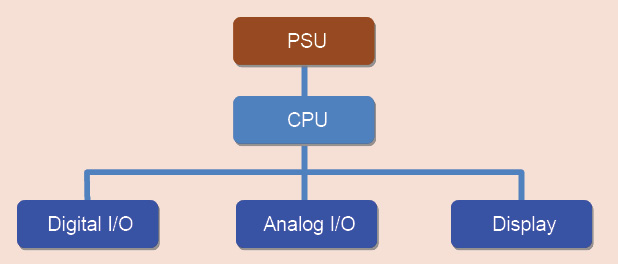
Fig. 1 shows the block diagram of a conventional embedded system. As you can see, all components/peripherals are tightly-coupled around a CPU into a single entity. This entity can either be a printed circuit board (PCB) or a single chip [also known as system on chip (SoC)]. Typically, FT systems have critical functional components of the system duplicated (in complex and mission-critical applications, there will be multiple units). Most commonly used mechanism is the duplication of the CPU.