


 An antenna amplifier boosts a radio signal considerably for devices that receive radio waves. Many devices have an RF amplifier stage in their circuitry, that amplifies the antenna signal. The received signal is usually very low in amplitude and is not enough for the receiver circuitry, hence the signal booster. In this project, we discuss a FM booster that can be used to listen to programs from distant FM stations clearly.
FM booster circuit assembly
The circuit comprises a common-emitter tuned RF pre-amplifier wired around VHF/UHF transistor 2SC2570. (Only C2570 is annotated on the transistor body.) Assemble the circuit on a good-quality PCB (preferably, glass-epoxy). Adjust input/ output trimmers (VC1/VC2) for maximum gain.
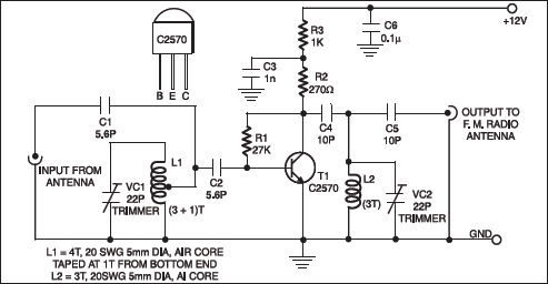
Input coil L1 consists of four turns of 20SWG enamelled copper wire (slightly space wound) over 5mm diameter former. It is tapped at the first turn from ground lead side. Coil L2 is similar to L1, but has only three turns. Pin configuration of transistor 2SC2570 is shown in the figure.

More interesting projects available here.
Please provide information about input antenna.
Use Dipole anthina it’s very good for fm reception also.mainly dipole used for fm transmission . But it also get sure reception in receiving . Trust me
From where Fm Booster can purchase