
 A frequency counter measures the frequency of an input signal. These are commonly used in laboratories, factories and field environments to provide direct frequency measurements of various devices.
Most frequency counters work by using a counter that accumulates the number of events (oscillations) occurring with in a specific period of time (say, one second). After the preset time period, the value in the counter is transferred to a display and the counter is reset to zero.
Frequency counter circuit
Fig.1 shows the circuit of a frequency counter built around timer NE555, decade counter/divider CD4033, 7805 regulator, 7-segment display and a few discrete components. Five decade counter- cum-7-segment-driver ICs (each CD4033) are connected in tandem to form a 5-digit decimal counter. IC CD4033 consists of a 5-stage counter and an output decoder that converts the code into a 7-segment decoded output for driving one stage of a numerical display.
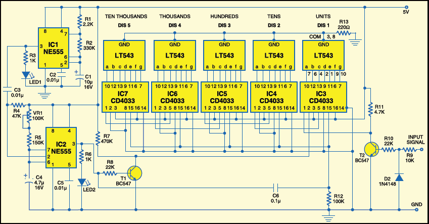
The sinewave signals coming from the oscillator source are first converted into positive-going pulses with the help of transistor T2 and diode D1. These pulses are then counted by the 5-digit decimal counter.

If pin 2 of IC3 is at logic ‘0,’ each pulse from the oscillator advances the counter by one. The logic condition of pin 2 is dependent upon the output of the monostable multivibrator built around IC NE555 (IC2).
IC555
The NE555 is a highly stable controller capable of producing accurate timing pulses. The time period of the monostable multivibrator is determined by the combination of resistor R5, preset VR1 and capacitor C4. Here it is set precisely to one second.

The monostable multivibrator is triggered by the astable multivibrator built around another IC NE555 (IC1). The time period of the astable multivibrator is determined by the combination of resistors R1 and R2 and capacitor C1. Here IC1 is designed to output a square wave having two second ‘high’ and two-second ‘low’ periods.
Circuit operation
The monostable multivibrator (IC2) is triggered whenever the output of the astable multivibrator (IC1) goes low. The output of IC2 instantly goes high and remains high for one second. Transistor T1 inverts the output of IC2 to make input pin 2 of IC3 low.
As soon as IC2 is triggered, the leading edge of the positive-going output pulse sends resting signal to all the decade counters via capacitor C6. The five 7-segment displays (DIS1 through DIS5) now show the count as ‘00000.’ As pin 2 of IC3 is low, the counter is enabled to count for one second. It continues counting the input pulses as long as the output of IC2 remains high.
After one second, the output of IC2 becomes low again. Transistor T1 is cut-off, prohibiting further counting by pulling up pin 2 of IC3 to logic ‘1.’ The number of pulses counted so far is displayed over 7-segment displays.
The process repeats, as long as power is applied to the counter circuit. Pin 5 of timer NE555 is the control voltage pin that is primarily used for filtering when the timer is used in noisy environments. However, by imposing a voltage at this pin, it is possible to vary the calculated period. A 0.01μF capacitor connected to pin 5 of NE555 bypasses any noise from altering the calculated pulse-width. LED2 indicates the counting period.
Power supply circuit
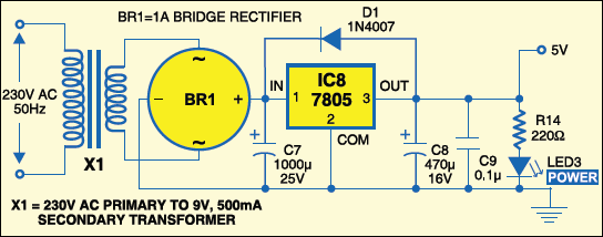
Fig. 2 shows the power supply circuit. The 230V, 50Hz AC mains is stepped down by transformer X1 to deliver a secondary output of 9V, 500mA. The transformer output is rectified by full-wave rectifier BR1, filtered by capacitor C7 and regulated by IC 7805 (IC8). The regulated 5V DC so obtained is further filtered by capacitors C8 and C9. LED3 acts as the power indicator. Resistor R14 acts as the current limiter. A capacitor above 10 μF is connected across the output of the regulator IC, while diode D1 protects the regulator IC in case its input is shorted to ground.
Construction & testing
Assemble the circuit on a printed circuit board (PCB) to minimise time and assembly errors. A single side PCB for the frequency counter is shown in Fig. 3(View as PDF) and its component layout in Fig. 4(View as PDF)
Download PCB and component layout PDFs (Fig. 3, 4): click here
Carefully assemble the components and double-check for any overlooked error. Use a low-capacitance cable to feed signal from the oscillator source to the frequency counter. Connect a known-frequency source (like calibration signal of an oscilloscope) to the input of the counter and adjust trimpot VR1 to display the frequency on the 7-segment displays.
The article was originally published in March 2010 and has been recently updated.


why is the units from right to left? can this not be moved or will it interfree with the rest
of circuit?
Thanks for the circuit but it given an output in a multiple of two i.e for 10HZ is given 20HZ as is reading
thank for the circuit, i’m trying to simulate it using protues but i’m having trouble with the input i tried connecting the power supply but the circuit still doesn’t count…help anyone !
Thanks for the feedback! We have not tried it on Proteus software but it was working well on the breadboard.
Thank you very much for your beautiful work.i want to know frequency max it measure. Thanks for answer JML
COUNTER IS NOT RESET TO ZERO ,FREQUENCY IS ADD TO THE PREVIOUS FREQUENCY.WHAT SHOULD I DO?