
Described here is a simple way to load a program without bootloader. An additional thing needed is a USB to Serial/UART/TTL adapter (3.3V level). Connect the USB to Serial board as follows, and power up the STM32 board from a USB port/power supply.
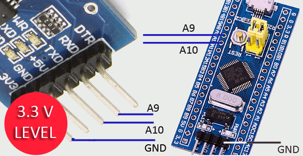
• RXD – A9
• TXD – A10
• GND – GND
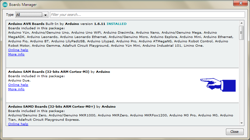
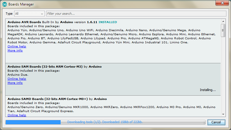
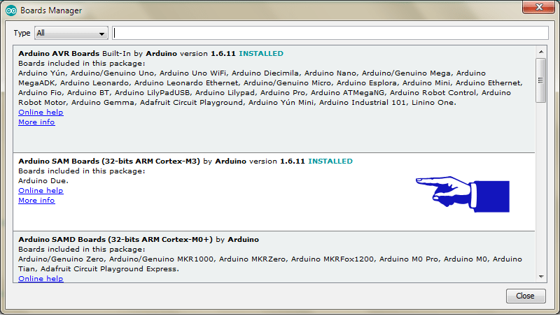
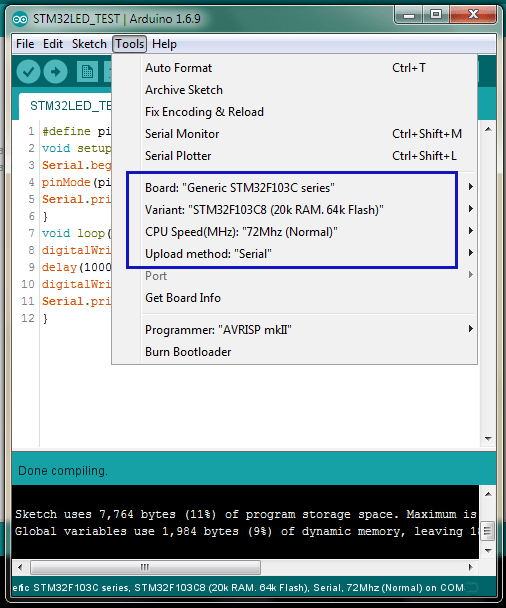
I assume you have already installed the Arduino IDE. Next, you need to go to ‘Board Manager’ under ‘Tools’ and install the support for SAM boards. Download the necessary files as well as the “Arduino_STM32’ (from the link). Extract “Arduino_STM32’ and copy the folder ‘Arduino_STM32-master’ to your Arduino ‘Hardware’ folder. Finally, restart the Arduino IDE, choose correct board settings, compile the given sketch, and upload it. Before uploading, set the onboard ‘BOOT0’ jumper to 1, and press ‘reset’ button. After upload completed, the sketch will run. If you want the uploaded sketch to run automatically after next power on/reset, set ‘BOOT0‘ jumper back to 0.
[stextbox id=”grey”]

#define pinLED PC13
void setup() {
Serial.begin(9600);
pinMode(pinLED, OUTPUT);
Serial.println(“START”);
}
void loop() {
digitalWrite(pinLED, HIGH);
delay(1000);
digitalWrite(pinLED, LOW);
Serial.println(“Hello World”);
}
[/stextbox]
How to use the onboard USB interface?
While the STM32F103 board is very popular and inexpensive, getting up and running is a knotty task. Since, the generic STM32 board comes only with the default USART boot loader, you cannot use its onboard USB interface to program it. However, if you are ready to program the board with a USB boot loader via USART, you can program it directly through the USB interface thereafter!

The ‘STM32duino bootloader’, is an experimental bootloader, based on the Maple bootloader (developed by LeafLabs), however it also works with most Generic STM32 board. There are 2 main versions of the bootloader, and within the generic bootloaders (versions starting with the word “generic”) there are different versions depending on the location of the LED on the generic board. For example, ‘generic_boot20_pc13.bin’ is suitable for the most common generic boards with an LED on pin PC13. Note that there is already a page in the wiki about the bootloader which includes how to flash it – link. Also refer this link
For bootloader flashing, connect your USB to Serial/UART/TTL adapter as done before. The onboard yellow jumpers (BOOT0 and BOOT1) specify the source of code for the micro-controller, and in the default state (both being 0), the microcontroller uses its own flash memory bootloader (there is nothing right now). Here, you need to set BOOT0 jumper as 1 and leave BOOT1 to 0.
• Download the demonstrator gui (STM32 flasher)
• Keep your board connected to PC
• Open demonstrator gui (STMFlashLoader Demo) executable file. Select 115200 Baud rate and select the correct COM port (leave all other settings as default)
• Press NEXT and after the automatic board detection, Press NEXT twice
• Select download to device and browse to select generic_boot20_pc13.bin file (in the
• STM32duino_bootloader folder)
• Press NEXT when the bootloader file is loaded and the file will be downloaded to the board. Close STM32 flasher when done
• Open your Arduino Sketchbook folder. Then open Arduino_STM32 folder – drivers – win, and run “install_drivers.bat” as administrator. Press any key to close when done. Then run “install_STM_COM_drivers.bat” as administrator, too
• Connect boot0 to 0, disconnect USB to Serial/UART/TTL board and connect a microUSB cable to the board.
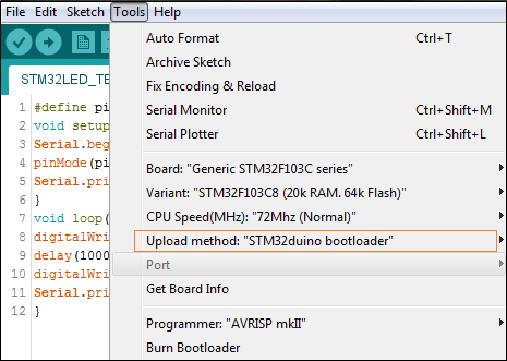
Now you can find Windows is installing driver for the board when you connect it to PC using the onboard microUSB. Eventually a driver named as “maple DFU” will be installed (without any COM ports assigned to it because of the perpetual bootloader). Now you can upload the blink sketch through Arduino IDE (as we done before, but now through USB; upload method – STM32duino bootloader).
If the sketch uploads successfully, you can find that Windows is installing a new driver and this time it will assign one COM port for the board. Note down it as it’s necessary to select the correct COM port to upload sketches from now on. Note that usually you have to reset the board every time you are about to upload code, but with the bootloader installed you don’t have to reset the board while uploading code anymore.
Experienced Issues
Sometimes this bootloader flashing process may not work with a generic STM32 board. If it doesn’t appear on USB at all, check there’s a pull-up resistor of around 1.5KΩ on PA12 (USB line D+) of the board. If not, just add one there, as unless you are ready for some tinkering, these boards may not work with the bootloader. Further, although the USB standard requires a 1.5 KΩ pullup resistor on D+, some board is known to have a wrong value of 4K7/10K (R10) resistor. However, it is also true that some PCs are tolerant of incorrect resistor value, you can try if it works before changing the resistance value to 1.5 KΩ.Surprisingly, we can compare this little board with Arduino Due to some extent as this nifty board has a promised CPU Speed of 72Mhz! Thanks to the work made by the stm32duino community and to the support of ST itself, now STM32 microcontrollers can be easily used with the Arduino IDE and it’s also possible to take advantage of most of the libraries available for Arduino. However, for novices it might be difficult to use just because handling embedded development tools like KEIL isn’t easy for them. There’s a serious lack of ample documentation on it and everything available in the internet is quite scattered. So, here’s something to get them set off easily. Have fun!!!
Download source code
Interested in STM32 board! Check out other projects in the circuits section.


