
 Atmel’s AVR microcontroller chips are in-system programmable (ISP), i.e. these can be programmed directly in the target circuit. A special programmer software is used to download the program from the PC into the AVR’s flash memory. Atmel offers a software package called the Atmel AVR ISP that allows programming of the AVR microcontrollers in the circuit using a simple dongle. The Atmel AVR ISP dongle is an adaptor cable that connects the PC’s parallel port with the ISP pins of the AVR chip for programming.
For programming, the four lines adaptor (dongle) are:
1. MOSI (Master Out, Slave In): Data being transmitted to the AVR being programmed is sent on this pin
2. MISO (Master In, Slave Out): Data received from the AVR being programmed is sent on this pin
3. SCK (Shift Clock): Serial clock generated by the programmer from the PC.
4. RST (Reset): Reset (low pulse) generated by the program. The AVR is programmed while in reset state.
Atmel AVR ISP Dongle
Here’s an Atmel AVR ISP dongle circuit for in-system programming of Atmel’s AVR chip AT90S8515 using such software packages as Atmel ISP 2.65 and PonyProg2000.
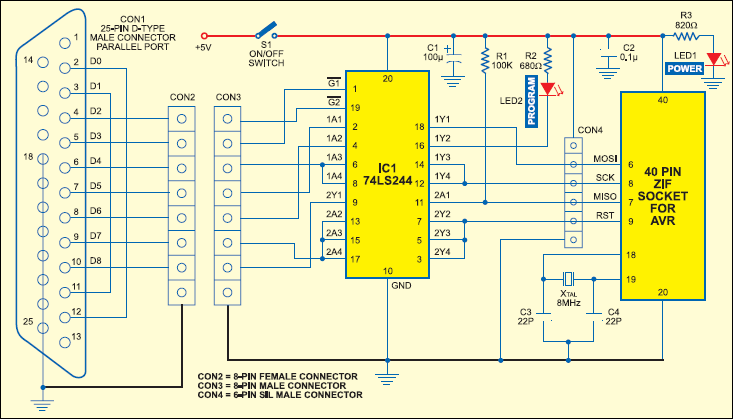
The PC’s parallel-port pins 4 and 5 drive buffer IC 74LS244 by enabling its pins 19 and 1, respectively. A low pulse on these pins will allow the passing of the serial clock and data during programming. MOSI, LED, SCK and RST outputs are buffered from the parallel port’s pins 7, 8, 6 and 9, respectively. The MISO input from the AVR is fed into pin 10 of the parallel port.
IC 74LS244 (IC1) acts as a buffer as well as an isolator circuit when the AVR is not in programming mode. In idle mode, all the outputs are tristated so as not to affect the operation of the target system.

Circuit operation
When the AVR’s ISP mode is selected, the lower half of IC 74LS244 is enabled, pulling the target system’s Reset line low. Once the target system is in Reset mode, the SCK, MISO and MOSI lines are no longer loaded by the peripheral circuitry, if any, on the target system. Now, it is safe to enable the upper half of 74LS244, driving the MOSI, LED and SCK lines of the dongle. The RST pin becomes high after the AVR is programmed. Glowing of LED2 indicates that the AVR is in programming mode.
There are two standard connectors for in-system programming of Atmel AVR microcontroller. One is the 10-pin header (dual-in-line (DIL) connector)) used on the Atmel STK kits. The other is a 6-pin header (DIL connector) used in Atmel ISPs. The two loop-back connections, pin 2-to-pin 12 and pin 3-to-pin 11 of the parallel port, are used to identify the dongle. With only pin 2-to-pin 12 link, the dongle is called STK300 or AVR ISP dongle. The dongle is called STK200 or old Kanda ISP dongle, with only pin 3-to-pin 11 link. With both links in place, the dongle is identified as a value-added pack dongle.
Here, we’ve used an 8-pin single-in-line (SIL) connector and an additional 6-pin SIL connector for the Atmel programer circuit. With the buffer and the 40-pin ZIF socket in this circuit, it can be used as a standalone programmer. The 6-pin SIL male connector is used for connection between the dongle and the AVR on the target board. Thus, another 6-line cable of about 30cm length is required for connecting this ISP adaptor (dongle) to the target circuit.

Note
If the AVR is not on the target circuit, you can insert the AVR into the ZIF socket and program it. Regulated 5V DC is required for the AVR and the associated dongle circuit, whose terminals are also provided in connector CON4. LED1 is used as the power indicator for the circuit.
The article was first published in February 2005 and has recently been updated.


