
A line follower robot with pick-and-placement capabilities is commonly used in manufacturing plants. These move on a specified path to pick the components from specified locations and place them on desired locations.
Basically, a line follower robot is a self-operating robot that detects and follows a line drawn on the floor. The path to be taken is indicated by a white line on a black surface. The control system used must sense the line and maneuver the robot to stay on course while constantly correcting the wrong moves using feedback mechanism, thus forming a simple yet effective closed-loop system.
Line follower robot circuit description
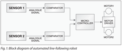
Fig. 1 show the block diagram of the automated line follower robot. It consists of mainly four parts: two sensors, two comparators, one decision-making device and two motor drivers. The robot is built using microcontroller AT89C51 (used as the decision-making device), motor driver L293D, operational amplifier LM324 (comparator), phototransistor (sensor) and a few discrete components.
In the circuit, the sensors (phototransistors) are used to detect the white strip on a black background. The sensor output is fed to the microcontroller, which takes the decision and gives appropriate command to motor driver L293D so as to move the motor accordingly.

Sensor. The sensor senses the light reflected from the surface and feeds the output to the comparator. When the sensor is above the white background the light falling on it from the source reflects to the sensor, and when the sensor is above the black background the light from the source doesn’t reflect to it. The sensor senses the reflected light to give an output, which is fed to the comparator.
Comparator. The comparator compares the analogue inputs from sensors with a fixed reference voltage. If this voltage is greater than the reference voltage the comparator outputs a low voltage, and if it is smaller the comparator generates a high voltage that acts as input for the decision-making device (microcontroller).
Microcontroller. The microcontroller is programmed to make the robot move forward, turn right or turn left based on the input coming from the comparator. The outputs of the microcontroller are fed to the motor driver.

Motor driver. The current supplied by the microcontroller to drive the motor is small. Therefore a motor-driver IC is used. It provides sufficient current to drive the motor.
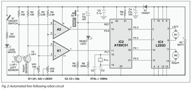
 Fig. 2 shows the circuit of the automated line follower robot. When light falls on the phototransistor (say, T1), it goes into saturation and starts conducting. When no light falls on the phototransistor, it is cut-off. A white LED (LED2) has been used to illuminate the white path on a black background. Phototransistors T1 and T2 are used for detecting the white path on the black background.
Collectors of phototransistors T1 and T2 are connected to the inverting inputs of operational amplifiers A2 and A1. The signal voltage at the inverting input of the operational amplifier is compared with the fixed reference voltage, which is formed by a potential divider circuit of 5.6-kilo-ohm resistor and 10-kilo-ohm preset. This reference voltage can be adjusted by changing the value of the 10-kilo-ohm preset.
When sensor T2 is above the black surface, it remains cut-off as the black surface absorbs virtually all the light falling from LED2 and no light is reflected back. The voltage at the inverting input (pin 2) of operational amplifier A1 is higher than the reference voltage at its non-inverting input (pin 3) and therefore the amplifier output at pin 1 becomes zero.
When sensor T2 is above the white line, the light gets reflected from the white surface to fall on phototransistor T2. Phototransistor T2 goes into saturation and conducts. The inverting input (pin 2) of operational amplifier A1 goes below the reference voltage at its non-inverting input (pin 3) of operational amplifier A1 and therefore output pin 1 goes high. This way, the comparator outputs logic ‘0’ for black surface and logic ‘1’ for white surface.
Similarly, comparator A2 compares the input voltage from phototransistor T1 with a fixed reference voltage.
The outputs of operational amplifiers A1 and A2 are fed to microcontroller AT89C51. The AT89C51 is an 8-bit microcontroller having 4 kB of Flash, 128 bytes of RAM, 32 I/O lines, two 16-bit timers/ counters, a five-vector two-level interrupt architecture, on-chip oscillator and clock circuitry. A 12MHz crystal is used for providing the basic clock frequency. All I/O pins are reset to ‘1’ as soon as RST pin goes high. Holding RST pin high for two machine cycles while the oscillator is running resets the device. Power-on reset is derived from resistor R5 and capacitor C1. Switch S2 is used for manual reset. The microcontroller, based on the inputs from sensor T1 (say, left) and sensor T2 (say, right), controls the motor to make the robot turn left, turn right or move forward.


Need complete fritzing circuit diagram
how to order line followed robot
Need source code
Hi Jahangir, the Source Code is present at the end of the article.
need step by step assembly of the circuit
Nice project.
But Ambiguity is, Can we use at89s51 or at89s52 instead of at89c51 microcontroller for this project?
And tell me that, How can i programme microcontroller ? Step by step
PCB and component layout PDFs are not working.
Kindly temporary turn off the antivirus on your computer and redownload