


Inconvenience in switching on a water pump installed in a remote farm is a common problem faced by farmers. Many circuits have been developed to solve this problem. Most of them are expensive and microcontroller based. Here we present a cellphone based water pump remote controller that can be operated by a phone call. By calling the cellphone attached to the controller, the water pump can be directly activated.
Cellphone based water pump remote controller circuit
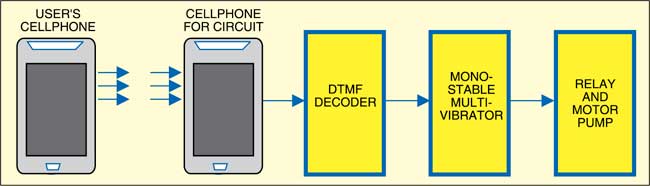
Fig. 1 shows the block diagram of cellphone based water pump remote controller. Fig. 2 shows the detailed circuit. The circuit is built around DTMF decoder IC MT8870 (IC1), timer NE555 (IC2) wired as monostable multivibrator and a few discrete components. The main component of the circuit is IC MT8870. This DTMF decoder has band-split filter and digital decoder functions. It offers the advantages of small size, low power consumption and high performance.
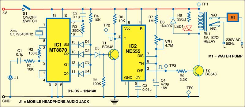
Once monostable timer IC2 is triggered, its output goes high for the preset time period. The time period depends on the values of resistor R7 and capacitor C4. It can be adjusted between 8 and 50 minutes using pot-meter VR1. The high output at pin 3 of IC2 energises relay RL1 to switch on the water pump.

The triggering pulse for IC2 is generated by DTMF decoder IC1 and the arrangement of diodes D1 through D5. Std pin of IC1 provides a high pulse when a valid tone-pair is received. Transistor T1 conducts only when outputs Q0 through Q2 and Std are high simultaneously. This can be achieved by sending digit ‘7’ through DTMF.
The water pump controller is connected to a dedicated cellphone through connector J1 with auto-answering mode enabled. The DTMF signal sent from the user end is decoded by the DTMF decoder and the corresponding binary-coded decimal (BCD) value appears on outputs Q0 through Q3. In this circuit only three of them are used.
Working of the circuit is simple. To switch ‘on’ the water pump, call the cellphone connected to the controller circuit and press ‘7’ once the ring stops. LED1 will glow to indicate that the water pump is switched on. The water pump turns off automatically after the preset time. LED1 turns off simultaneously.
Construction and testing
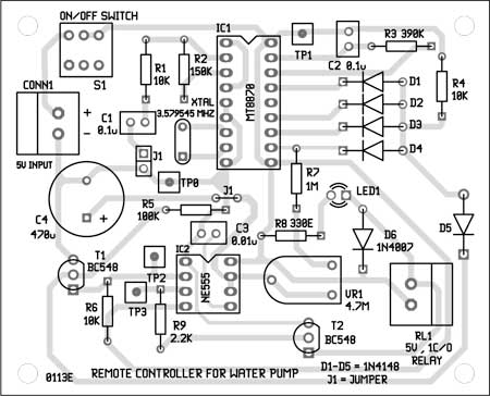
An actual-size, single-side PCB for cell-phone-based remote controller is shown in Fig. 3 and its component layout in Fig. 4. Suitable connector is provided on the PCB to connect the cellphone. Assemble the circuit on a PCB to minimise time and assembly errors. Carefully assemble the components and double-check for any overlooked error. Use suitable IC socket for MT887 and NE555 ICs.
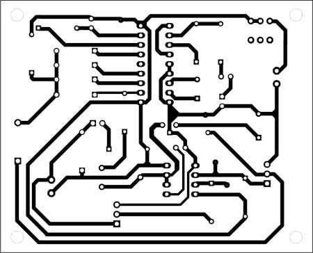
Download PCB and component layout PDFs: click here
Use relay RL1 with contact current rating capable of carrying the water pump’s current.
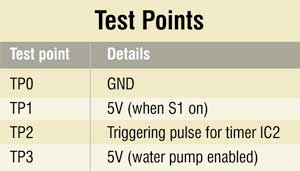
To test the circuit for proper functioning, press switch S1 and verify 5V at TP1 with respect to TP0. Connect the cellphone to the controller using connector J1. Call this cellphone and press ‘7’ once the ring stops. At the same time, verify high-to-low triggering pulse at TP2. TP3 now should be high for the preset time period.

Thanks for the circuit. I was looking for something like that. But i wanted to know that whether there is anyway to switch off the pump once it is started besides the timer circuit.
Any mobile operate it.
and what privacy related with start and stop system
This Project was Tested ?
Yes, This project is fully tested.
Thanks EFY Team,
But I want a circuit that can turn on and off both remotely.plz help…
Can be used HT9170 instead of MT8870?
how to connect cellphone with this ckt.i made this ckt for my mini project but i dont know how to connect plz reply fast
First connect audio jack to the mobile, say mobile1. Then connect the other end of the jack to the circuit at J1 as shown in Fig.2 above. Now, to turn on the pump, dial the mobile1 number from another mobile, say mobile2. When the call between mobile1 and mobile2 is established, press 7 key from mobile2.
I want purchase circuit of cellphone based remote conroller
I want purchase this whole cricut of cellphone based motor control
Contact number…plzz
How to connect 3 phase motor starter?
Sir please any reply
Can we use CM8870 DTMF decoder instead of MT8870 ? Please reply with answer Thank you.
Yes, you can use CM8870 in place of MT8870.
Sir i am interested in gsm based motor starter auto manufacturer
please batayenge Yeh circuit kaun se mahine Mein publish hua tha
This article was published in January 2013.
This Project requires any programming ??
Hi Harish, this Project doesn’t require a source code.
Will this project will also work for 3 phase motor ??
1.Will this project also work for 3 phase motor ?
2. Is any programming required in this project ?
I want a circuit diagram of three phase motor on off by cellphone with voice. please provide
This project work on 3 phase motor control? How?
Can you please give information up to 10 to 15 pages ??
Because of my project is this
And l collect information up 10 pages
Kindly elaborate your query.
Is this project:-
Cellphone-Based Remote Controller for Water Pump
Still available
And would it still work on current day mobile phones in 2019?
Hello
Actually I wanted to ask that I made the whole on bread board n it’s not working n I rechecked the all the connections n still it’s not working what I should do to troubleshoot that.
I kindly request you to revert back as soon as possible.
Thank you
Hello
I just wanted to ask that I connected the whole circuit according the circuit provided by you on a bread board but it’s not working and I rechecked all connections but it’s not not working.
Can you please provide me the solution for troubleshooting as soon as possible.
Thank you
Are you getting the voltages as shown in the test point table? Please note that a non-defective MT8870 IC should indicate proper binary values across output pins (Pins 11 through 13) corresponding to the decimal number pressed on your telephone keypad. Whenever you press telephone button, you should get a pulse at std pin 15. You may also replace MT8870 and try again.
Hi
Actually that time I got all the tests correct except for TP3 but to correct it I reconnected that IC n now I m even get the triggering pulse.
I would really appreciate any suggestion regarding that.
Thank you
Give a negative pulse at pin 2 of 555 IC by connecting it to ground temporarily and then check high pulse at pin 3 of 555. If you are not getting high pulse at pin 3, check its connection or replace it with a fresh one.
Latest cell phone starter circuit diagram
This is a 4-year-old circuit diagram. You can use this diagram as well.