


 This project describes the designing 8 bit ALU using Verilog programming language. It includes writing, compiling and simulating Verilog code in ModelSim on a Windows platform.
In digital electronics, an arithmetic logic unit (ALU) is a digital circuit that performs arithmetic and bit-wise logical operations on integer binary numbers. It is a fundamental building block of the central processing unit (CPU) found in many computers and microcontrollers.
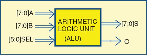
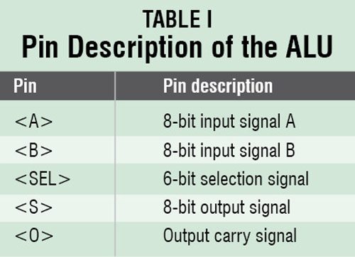
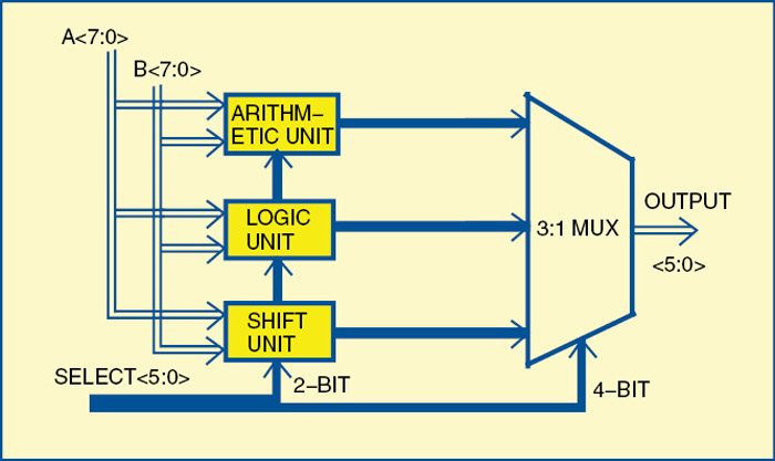
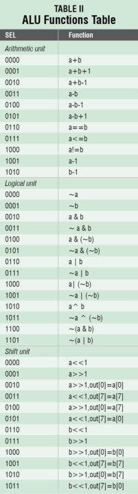
Inputs to an ALU are the data to be operated on (called operands) and a code indicating the operation to be performed, while the ALU’s output is the result of the performed operation. In many designs, the ALU also exchanges additional information with a status register, which relates to the result of current or previous operations. The pin diagram of the ALU is shown in Fig. 1 and its description in Table I. The ALU architecture is shown in Fig. 2 and its function tables are listed in Table II.

Designing 8 bit ALU
ModelSim is an easy-to-use, versatile VHDL/SystemVerilog/Verilog/SystemC simulator by Mentor Graphics. It supports behavioural, register-transfer-level and gate-level modelling.
First, install ModelSim on a Windows PC.
1. Start ModelSim from desktop; you will see ModelSim 10.4 dialogue window.
2. Create a project by clicking Jumpstart on the Welcome screen.
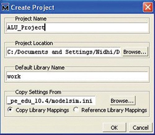
3. A Create Project window pops up (Fig. 3). Select a suitable name for your project.
Set Project Location to C:/Documents and Settings/Nidhi/Desktop/Final_ALU_Testing (in our case) and leave the rest as default, followed by clicking OK.
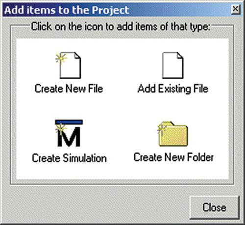
3. An Add items to the Project window pops up (Fig. 4).
4. On this window, select Create New File option.
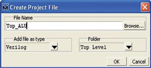
5. A Create Project File window pops up. Select an appropriate file name (say, Top_ALU) for the file you want to add; choose Verilog as Add file as type and Top Level as Folder (Fig. 5).
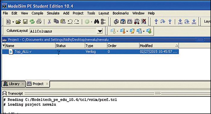
6. On the workspace section of the main window (Fig. 6), double-click on the file you have just created (Top_ALU.v in our case).
7. Type in your Verilog code (Top_ALU.v) for an 8-bit ALU in the new window.
8. Save your code from File menu.
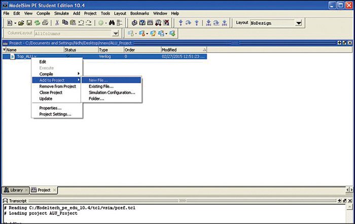
9. Now, add relevant files as per the architecture, which includes arithmetic, logic, shift and MUX units. Add new files to Top_ALU project by right-clicking Top_ALU.v file. Select Add to Project -> New File… options as shown in Fig. 7.
Give File Name Top_Arithmetic and follow the steps from five through nine as mentioned above.
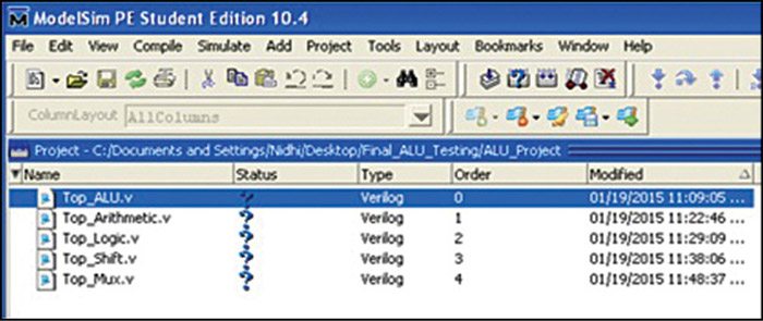
Similarly, add Top_Logic, Top_Shift and Top_Mux files into the project and enter respective Verilog codes in these files.
The final workspace window is shown in Fig. 8.
Compiling/debugging project files
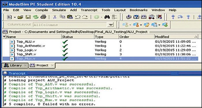
1. Select Compile->Compile All options.
2. The compilation result is shown on the main window. A green tick is shown against each file name, which means there are no errors in the project (Fig. 9).
Simulating the ALU design
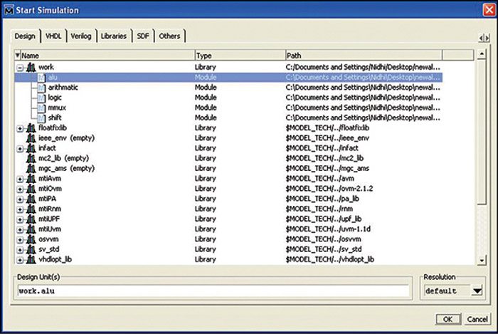
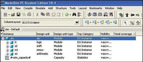
1. Click on Library menu from the main window and then click on the plus (+) sign next to the work library. You should see the name Top_ALU code that we have just compiled (Fig. 10).
2. Double-click on ALU to load the file. This should open a third tab sim in the main window.
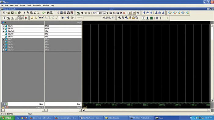
3. Go to Add ->To Wave-> All items in region options (Fig. 11).
4. Select the signals that you want to monitor for simulation purposes. Select these as shown in Fig. 12.
5. Provide values manually to monitor the simulation of the eight-bit ALU design.
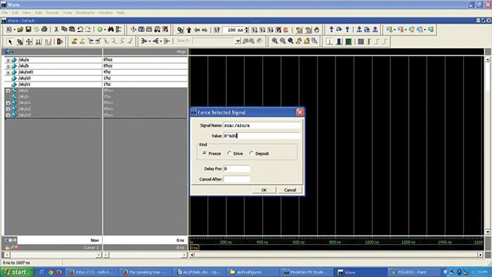
Right-click on the selected signals and click on Force (Fig. 13).
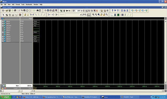
After providing values to selected signals, we are now ready to simulate our design by clicking Run in the simulation window as shown in Fig. 14.
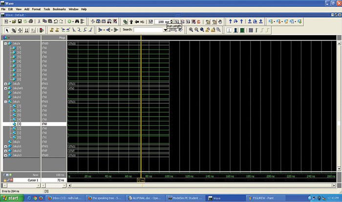
Now, click on Zoom Full from the wave window. Your simulation output waveform will be as shown in Fig. 15.
Thus, the result of the ALU design is verified from this output waveform.
Download Source Code: click here
Future applications
The ALU described here can be further refined to make more advanced-level projects with some more complex logics in order to handle complex calculations in the CPUs.
Hadfun designing 8 bit ALU? Check out other verilog projects.
