
This is a simple circuit that activates an alarm when there is a knock on the door or there are any vibrations due to movement of heavy goods or furniture. The circuit uses readily available components.
Circuit and working
The circuit is built around quad-opamp LM324 (IC1), which is configured in amplifier mode. It uses the piezoelectric element of a piezo buzzer as the input sensor, two transistors BC547 (T1 through T2), a piezo buzzer and some other components for the alarm circuit. Fig. 1 shows the circuit diagram of the door-knock alarm.
The reference voltage at pin 3 of IC1 is set by trimming potmeter VR1. The piezoelectric element plate is fixed at the centre of the door using cello tape. Apply a small quantity of adhesive on the edges between the plates. Wires from the piezo element are connected at CON2. These generate an input pulse when vibrations are caused by knocking on the door. The pulse is amplified by op-amp A1 of IC1. Remaining three op-amps of quad IC LM324 are not used here.
The output of A1 of LM324 from pin 1 is further amplified by transistors T1 and T2 to drive the piezo buzzer or relay. Because of the presence of high-value capacitor C5, the buzzer remains active for a few seconds. The circuit is powered by 9V/12V power supply. Sensitivity of the circuit can be adjusted by 1M potmeter VR1.

In place of piezo buzzer PZ1, you can use 9V/12V single-changeover relay connected to an amplifier for louder sounds.

Construction and testing
An actual-size, single-side PCB for the alarm is shown in Fig. 2 and its component layout in Fig. 3. After assembling the circuit on the PCB, enclose it in a suitable plastic box.
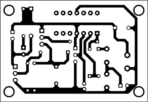
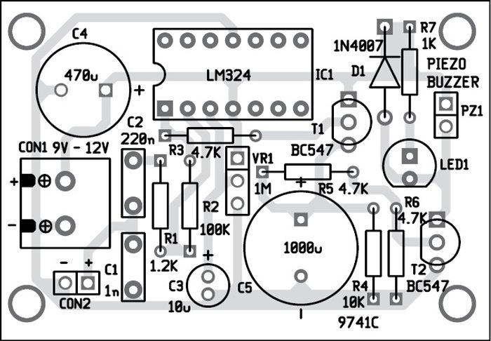
Download PCB and component layout PDFs: click here
Before using the circuit, ensure that supply voltage is correct.

The author is B.Sc. physics graduate and a regular contributor to various magazines


