
Fire is like a double-edged sword. Discovery of fire stands as a milestone in the history of mankind. Fire fighters try their best to fight and extinguish fires when in need. But at the household level, it is observed that if the fire can be extinguished at an early stage, many major accidents can be averted. The aim here is to build a fire extinguishing robot that can help in-case fire breaks out.
Circuit and working
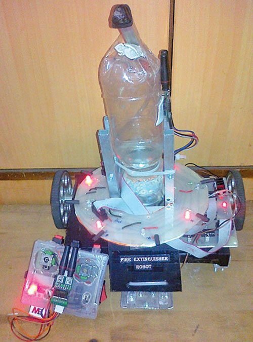
This fire extinguishing robot is a prototype (Fig. 1) of the actual one. Sensors used here are simple infrared (IR) photodiodes that detect IR rays coming out of the fire. The sensor board mounted on top of the robot’s chassis is circular in shape so that it gives the robot all-round detection view of 360°. Sensors are equally spaced at 45° each. These act as the eyes of the robot.
In the actual robot, use of fire sensors or IR cameras is recommended. But these are too expensive and hence IR photodiodes have been used as a substitute in the prototype.
The pump used here symbolises the fire extinguishing mechanism, and is used as a substitute in the prototype. Also, the body used is not fire-proof. The actual robot must use fire-proof material for proper and better functioning for efficient results.
IR waves
Wavelengths longer than visible and up to 1mm are termed as IR waves. IR radiation can be felt as radiant heat, for example, when you stand in front of a fire.

The light emitted by a burning source comprises IR waves, so by using IR photodiodes as sensors we can detect a fire. This principle has been used in the designing of the sensor board.
DC water pump
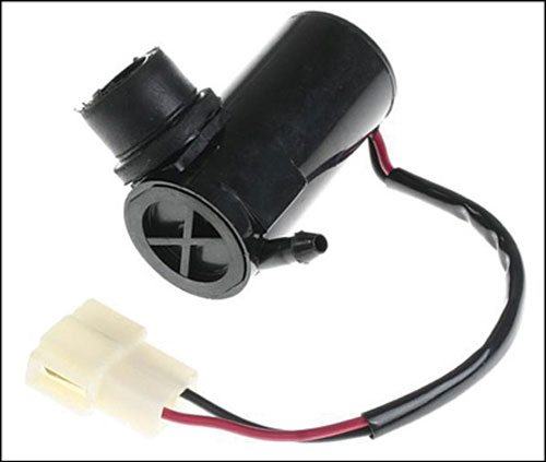
A DC water pump is used for the purpose of extinguishing fire. It pumps out water stored in a bottle. The DC water pump is shown in Fig. 2. Any other suitable water pump can also be used.
RF module
A pair of 433MHz RF transmitter-receiver module is used. It allows transmission and reception of serial data without physical connection. The frequency of an RF signal is inversely proportional to the wavelength of the field.

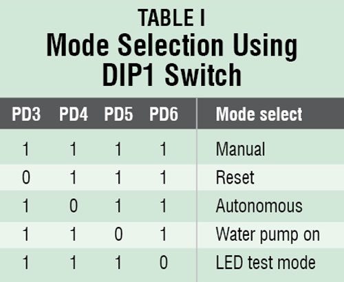
The robot can be made to work in manual as well as in autonomous mode. (Manual mode was tested at EFY Lab.) Different modes of operation are given in Table I. The fire extinguishing robot works in three stages.
Stage 1: Fire detection (autonomous mode)
IR photodiodes are connected in reverse bias as shown in the circuit diagram of the sensor module (Fig. 3). Anodes are commonly connected to the ground and cathodes are connected to the 5V via resistors of 1MΩ each.
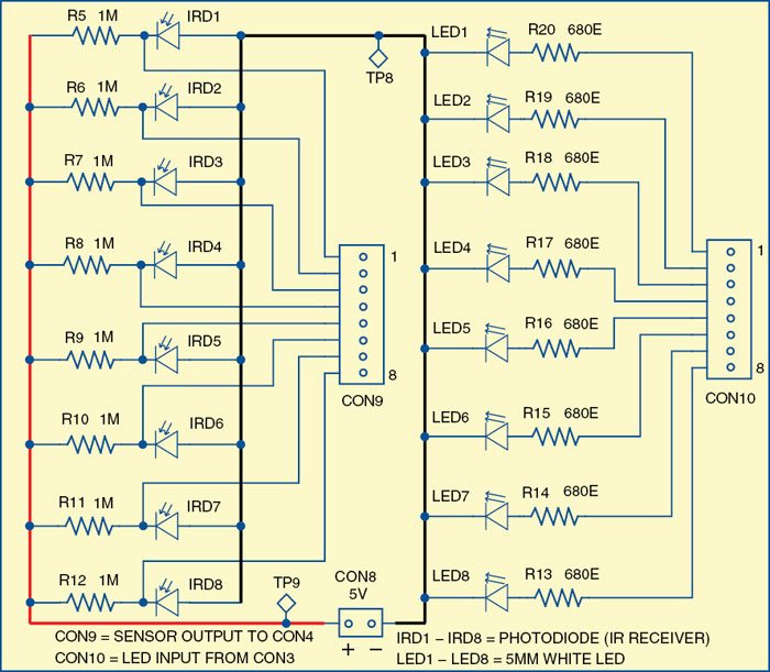
Voltage across the photodiode is given as input to ADC pins (PA0 through PA7) of ATmega16. When IR waves fall on the IR photodiode, its resistance decreases from 650kΩ to 150kΩ, reducing the voltage across the photodiode, thus changing the input voltage at the ADC pin. By proper quantisation, the presence and absence of the flame can be distinguished.
Similarly, eight IR photodiodes mounted in a circular fashion on the sensor board help detect the fire; the corresponding LED glows if fire is detected. The cone of detection of the IR photodiode is large, thus decreasing the resolution of the system. This problem can be solved by properly shielding IR photodiodes.
Code to detect the presence of fire using the ADC is as follows:
[stextbox id=”grey”]{
unsigned char v;
v= read_adc(0);
if(v>=0 && v <=128) //Stores the digital value of the analog voltage at ADC 0 fire_detected ( ); if(v>128 && v<=255)
fire_not_detected( );
}[/stextbox]
Stage 2: Extinguishing fire
Constant feedback from sensors is fed to the main module through CON4, and hence position of the fire with respect to the robot is determined. The main module includes an ATmega16 microcontroller, two L293D motor driver ICs to drive motors, a water pump and RF receiver RX1. The circuit diagram of the main module is shown in Fig. 4.
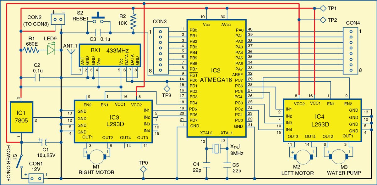
The basic function of the algorithm is to orient the front sensor in front of the fire so that the nozzle of the pump comes directly above the fire source. When this is achieved, the pump starts and extinguishes the fire.
The robot moves with the help of two motors, whose sense of rotation is controlled by the controller, depending on the feedback from the sensor.
Stage 3: RF communication and manual control (manual mode)
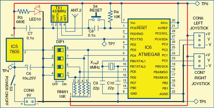
The robot is controlled by the operator with the help of a wireless remote (circuit diagram is shown in Fig. 5) that uses an RF module for communicating with the robot.
Switches, push buttons and joysticks are provided on the remote that controls various tasks such as autonomous mode selection, reset and starting the pump. For each command, the remote sends a specific character that is received by the robot and the corresponding operation is performed.
Specimen code for autonomous mode is given as below:
[stextbox id=”grey”]For remote (transmitter):
if(check_bit(&PIND,4)==0)
{
i=’h’; //auto mode
printf(“%c”,i);
}
For robot (receiver):
while(1)
{
scanf(“%c”,&ii);
_delay_ms(10);
switch(ii)
{
case ‘h’: //auto mode
autonomous();
break;[/stextbox]
Software program
Programming of the AVR is done using embedded C language. It is similar to C language but includes all functionalities of C as well as access to AVR pins, peripherals and controls. C code is converted to hex code using WinAVR.
Hex codes generated are burnt into MCUs for the main module (robot) and the remote module. Working of the program is explained as comments in the main module (robot) and remote module source codes.
The program jumps to the main function where the object code actually starts. At remote module, a DIP (DIP1) switch is interfaced using which you can select operating mode (autonomous or manual), switching of the water pump, reset all settings or LED indicators test mode as given in Table I.
Tools used are described below:
WinAVR
WinAVR is a suite of executable, open source software development tools for Atmel AVR series. It includes GNU GCC compiler for C and C++, Programmer’s Notepad, Makefile, etc.
Programmer’s Notepad (PN)
This is a source editor with some IDE features. PN can call any command-line tool and capture its output. It is ideal for calling make utility, which executes make file, which, in turn, calls the compiler, linker and other utilities used to build your software.
Makefile
WinAVR now includes MFile utility, an automatic make file generator for AVR GCC, which can run on various platforms including Windows, FreeBSD and Linux. You can use this utility to quickly generate make files for your project based on some simple menu input.
Construction and testing
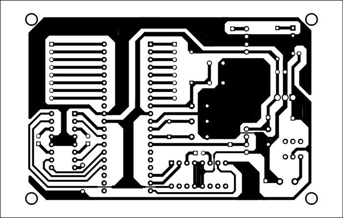
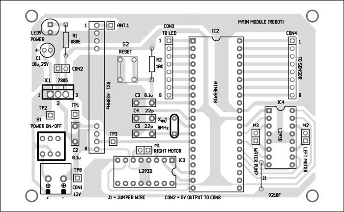
A single-side PCB of the main module is shown in Fig. 6 and its component layout in Fig. 7.
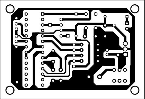
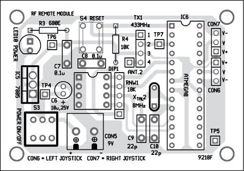
A single-side PCB of the RF remote module is shown in Fig. 8 and its component layout in Fig. 9.
Download PCB and Component Layout PDFs: Click here
Download Source Code: Click here
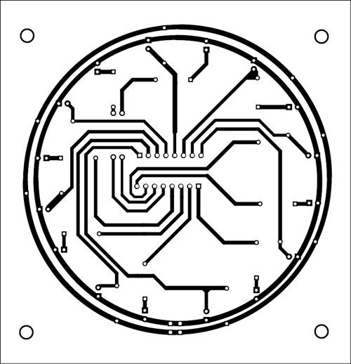
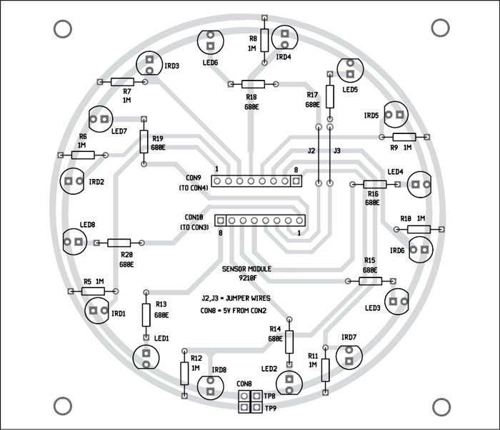
A single-side PCB of the sensor module is shown in Fig. 10 and its component layout in Fig. 11.
You can also assemble the circuit on a general-purpose PCB. Before mounting the MCUs on PCBs, burn respective codes into MCUs using a suitable programmer board.
After mounting all components on PCBs, switch on the power supplies of respective units.
At the main module (robot), initially four LED indicators glow on even pins of PORTB of IC2 by default, and the robot waits for the signal from RF remote. You can also test all the LEDs by pulling port PD6 of IC6 low through DIP1 switch.
For manual mode there are two joysticks connected at ADC channels of the controller (PC0 and PC1) at remote module. By using the joystick, robot movements can be controlled.
Move your robot towards the fire source. Pull PD5 of IC6 to low through DIP1 switch to switch on the water pump.
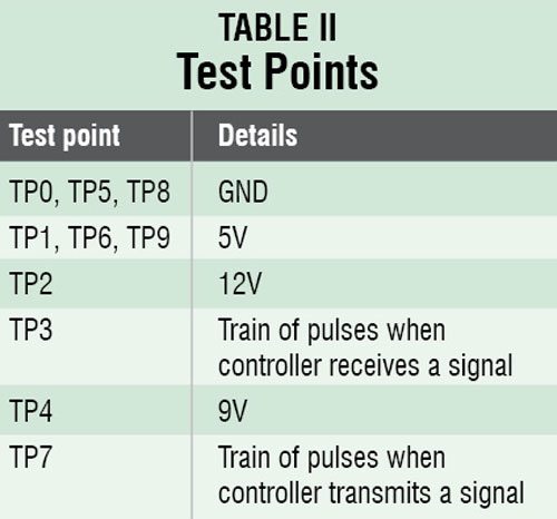
For troubleshooting the circuit, check to ensure voltages at various test points are as per Table II.
Applications
1. By replacing IR photo sensors with the thermal image-processing camera, the pump with a fire extinguishing mechanism and by making the body of the robot fire-proof, it can be used for fire extinguishing purposes. It can also be used in assisting fire fighters, thus helping them reach inaccessible places to save more lives.
2. Increasing the number of sensors will improve the resolution and accuracy of the system further.
3. In autonomous mode, it can detect a fire, if any, and extinguish it without any assistance.
4. The RF module makes it possible for the operator to control the robot manually from a distance, thus allowing surveillance facility.
Limitations
IR photodiodes also react to sunrays, just like fire, since these too contain IR waves, thus allowing the robot to make false judgments. However, the effect of sunlight and other factors is not significant if we use better sensors (which are far more costly).
Future enhancements
To improve the system:
1. Use more sensors such as smoke detectors, temperature sensors and thermal image processing for feedback and to improve the accuracy and reliability of the system further.
2. Replace IR photo sensors with more dependable ones, which have filters, because IR sensors even take sunlight as a source of IR waves, leading to errors and false alarms.
Amol Gulhane is B.Tech (electronics and telecommunication) from College of Engineering Pune, and is co-founder of Robolab Technologies


What is the fire detection range of the robot if we use IR photodiode for detection of the fire ?
During testing the range was about 10-15cm range.
how water pump will work
canu give me the working of the robot sir it is urgent I have a exhibition can u pls help me by following the working or HW it work I have exhibition on 3 November
Sir how can we increase the range of the detection .???
Sir If u dont mind ,can i know the total cost of the project.
send a program
The source folder is present within the article.
Very nice
sir pleease send the source code
It is already available at the end of the article.
Hi, may I know what simulator app is used in making the circuit diagrams? thank you. Looking forward to your response.