
 Presented here is a security system that uses an inexpensive laser torch which is usually available with a key ring. The advantage of this security lock is that you can use any laser torch or pointer that is easily available in toy shops. It employs minimal input keys and yet is very secure. It can be used as a door lock, briefcase lock or any other application related to an electronic locking system.
Circuit and working
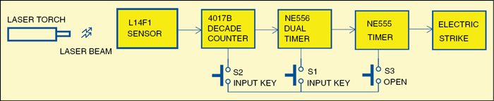
The block diagram of a laser-based security lock is shown in Fig. 1 and its schematic diagram in Fig. 2. Switches S1 and S2 work as security input keys and switch S3 is used for opening the lock manually. The lock can be an electric strike installed on the door frame to allow access with an access control system or any electronic remote control system.
Electric strikes are generally available in two configurations—fail-secure and fail-safe. In fail-secure configuration, applying electric current to the strike causes it to open; whereas in fail-safe configuration, applying electric current to the strike causes it to lock. A fail-secure configuration is used in this project.
Opening the lock. The use of switch S2, pressing and releasing of switch S1 and supplying the laser pulses at the right time are the security features of this circuit. Switch S2 should not be released during the entire operation, otherwise the counter will get reset and you will not be able to open on the lock.
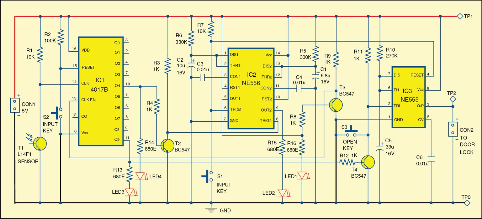
 When switch S1 is pressed, the first in-built timer of IC2 is triggered. Its output pin 5 goes high for four seconds. LED1 glows and transistor T3 conducts. During this time, the collector of T3 becomes low, which in turn pulls the clock enable pin (pin 13) of IC1 to low state. This enables the counter (IC1) to count. During this time, five laser pulses are applied (by you) at photo sensor T1. These signal pulses go to clock pin 14. LED4 glows and T2 conducts at the fifth pulse. This triggers the in-built second timer of IC2. Its output pin 9 goes high for two seconds. The high state is indicated by the glowing of LED2. When LED2 goes off, you press switch S1 and release it. The first timer is triggered again and its output is high for four seconds. During this time, you send another five pulses of laser beam towards the sensor. At the fifth pulse, LED3 glows and transistor T4 conducts. This action triggers IC3 and its output pin 3 goes high for ten seconds. That is, the lock opens for ten seconds.

The lock driver circuit is connected to output pin 3 of IC3. The circuit is powered off a 5V DC supply. Normally the electric lock or electric strike works off a 12V DC. To make the circuit simple, the lock driver section is not shown here.
Construction and testing
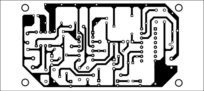
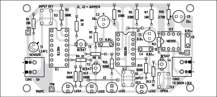
An actual-size, single-side PCB layout of the laser-based security lock is shown in Fig. 3 and its component layout in Fig. 4.
Mount the components on the PCB to avoid any assembly errors. Enclose the circuit in a suitable box. Mount switches S1, S2 and S3 at appropriate locations. If the circuit is to be used as a door lock, photo sensor T1, switches S1 and S2 should be mounted outside the door frame. The photo sensor should be enclosed in the box with a suitable contraption so that it can receive the laser beam properly. Switch S3 should be installed on other side of the wall near the door frame.

Download PCB and component layout component PDFs: click here
While pressing switches S1 and S2 simultaneously, point the laser torch toward the photo transistor sensor T1 and press on/off button of the laser torch five times within four seconds. Release switch S1 while pressing switch S2. Wait for two seconds till LED2 goes off. Keeping S2 pressed, press S1 and release it, press on/off button of laser torch five times again. The lock will open for ten seconds and then close automatically. The lock can also be opened from the inside (for ten seconds) by pressing switch S3.
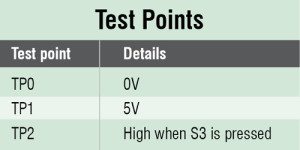
For troubleshooting, refer the test points table.
Read other exciting circuit articles


is there any equilant ic of 4017B ? Tell me please