


 Commercially available hearing aids are quite costly. Here is a low-cost hearing aid circuit that uses just four transistors and a few passive components.
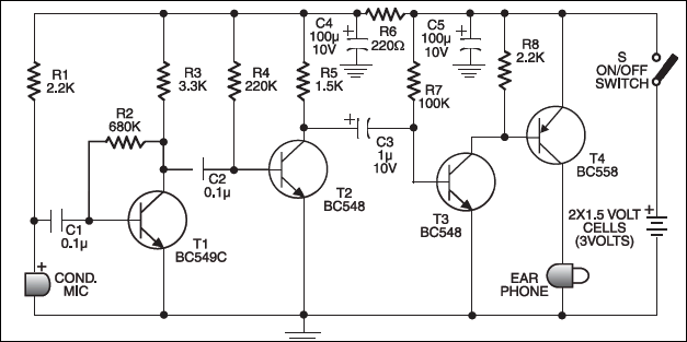
On moving power switch S to ‘on’ position, the condenser microphone detects the sound signal, which is amplified by transistors T1 and T2. Now the amplified signal passes through coupling capacitor C3 to the base of transistor T3. The signal is further amplified by pnp transistor T4 to drive a low impedance earphone. Capacitors C4 and C5 are the power supply decoupling capacitors.
Low-cost hearing aid circuit
The circuit can be easily assembled on a small, general-purpose PCB or a Vero board. It operates off a 3V DC supply. For this, you may use two small 1.5V cells. Keep switch S to ‘off’ state when the circuit is not in use. To increase the sensitivity of the condenser microphone, house it inside a small tube.

The article was originally published in August 2006 and has been recently updated.


I made the connections as per the circuit diag but there is no o/p on the earphone Why?
I may use any other special components?!