

The software program
Here serial communication is used to communicate with microcontroller IC1, and the microcontroller controls the device drivers. For the serial data transfer using RS232 protocol, the microcontroller and the PC should have the same baud rate. Here the baud rate is fixed at 9600 bits per seconds. With eight data bits and one stop bit, the parity is set as ‘none’ and the flow control is hardware in both the microcontroller and the computer. This is the basic setting for the serial data transfer used in this equipment controller project.
Two programs are used in this project. One is the firmware code for the microcontroller and the other is the user interface program.
Keil µVision is used for coding the firmware for the microcontroller and generating the hex code. The hex code can be burnt into the microcontroller using any compatible programmer board from Atmel, such as TopView programmer.
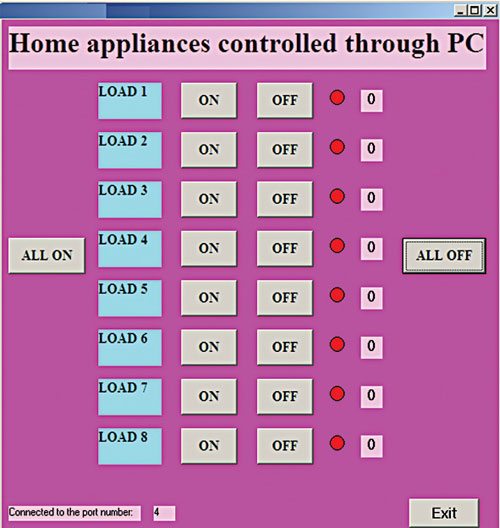
The user interface program to control the devices from the PC is developed using Visual Basic (VB) 2008, which has been chosen because it is user-friendly for designing GUI (graphical user interface) applications. Eight on and off buttons are used to control eight unique loads. Up to eight devices can be operated one after the other, or turned on/off simultaneously. The device’s on or off status is also shown by an indicator in the VB program.

Construction and testing
An actual-size, single-side PCB for PC-based electrical equipment controller circuit is shown in Fig. 3 and its component layout is shown in Fig. 4. Assemble the circuit on the PCB to save time and avoid assembly errors. Carefully assemble the components and double check for any short-circuit errors in the circuit. Burn the hex code into the microcontroller using a suitable programmer.
Use IC bases, especially for the microcontroller, on the PCB. Connect the assembled circuit to the COM port available on the back of the computer.
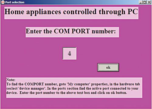
Run the VB program and you will see the welcome screen shown in Fig. 5. You need to enter the serial COM port in next screen. In this example, we have used COM 4 as shown in the screenshot in Fig. 6. Clicking the ‘OK’ button will lead you to the main control panel, where you can control the appliances using the mouse by clicking on the corresponding device’s button as shown in the screenshot in Fig. 7. You can either control the devices individually, or all eight at a time. If you click the ‘load1’ button, you will see low voltage at port pin 12 of the microcontroller. Then the first device will be turned on. Press reset switch S1 momentarily in case the device does not turn on. For more troubleshooting, refer to the test points listed in the table.

The author is in the third year of his BE (electrical and electronics) at Vickram College of Engineering, Madurai


Please share full source code..
Dear swanand, the source code is present on third page of the article.
can you please share vb code for the GUI application
You can download the complete source code including the VB code from here. http://www.efymag.com/admin/issuepdf/PC%20Based%20Electrical%20Equipment%20Control.rar
Hello sir,
How much time will it require to complete the whole working setup?
There is only Hex file available. Can you provide complete code of the micro controller?
where is the circuit diagram?
Dear Deepak Agarwal, the circuit diagram is present on the second page.
If you have to put a MicroController in the circuit to control 8 outputs from a PC, why not use Arduino? It can be interfaced with a PC with USB (Unlike this circuit which uses Serial port which is hard to find in PC today). No need to make circuit board because everything is on Arduino board.
Technology keeps on changing and so is serial com port. This article was published a few years back. But the fact is that you can find Serial Port in some Desktop PCs, server PCs, industrial PCs, etc. and if not PCI slots are available in them for adding Serial port cards.
hello sir,
i noticed that in pcb layout device 1 and and remaing 2to 8 device connected in different manner with traic but in circuit diagram they all are conected in same way
i think devic 1con is not correctly conected in pcb layout plzz tell me the layout is correct or not
thanks reply asap.
Thanks for pointing out the mistake! There is a wrong track connecting to TRIAC1 and DEVICE1. It has been corrected now. The corrected actual-size PCB layout is available in PDF format for download. To download it, you can click ‘Click here’ hyperlink given just below the PCB layout in this article.
How can I get all setup Including PCBs