
 There are several methods for controlling the speed of DC motors. One simple method is to add series resistance using a rheostat. As considerable power is consumed in the rheostat, this method is not economical. Another method is to use a series switch that can be closed/opened rapidly. This type of control is termed as chopper control. We’ve described here a PWM based speed control circuit that smoothly controls the speed of general-purpose DC motors.
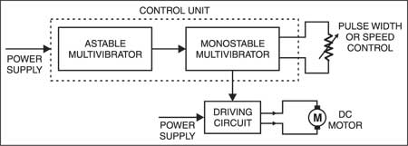
Fig. 1 shows the block diagram of a basic PWM-based chopper. The circuit shown in Fig. 2 is designed as per this diagram. A dual timer IC (NE556) is used to configure both the astable as well as the monostable multivibrator. Timing components for the astable are chosen to provide a frequency of 546 Hz, while the monostable components are selected to obtain a maximum pulsewidth of 2.42 ms. Diode D1 improves duty factor of the astable oscillator output, whereas D2 acts as a free-wheeling diode. Transistor SL100 drives the motor, while the 22-ohm, 2W resistor (R4) serves as a current limiter, avoiding overheating of the transistor. The DPDT switch enables direction reversal of the motor, as desired.
PWM based speed control circuit
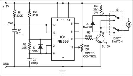
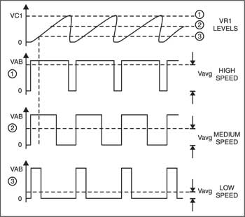
The speed can be varied by adjusting VR1, which changes the threshold value to which capacitor C1 in the monostable circuit is charged. This, in turn, determines its output pulse-width and hence the average voltage applied to the motor. Waveforms shown in Fig. 3 depict the average voltage for controlling various speeds.
For effective speed control, ‘on’ period (TON) of the astable should be equal to the maximum pulsewidth (TON) of the monostable.
For higher voltage and power requirements, SL100 can be replaced by an appropriate MOSFET or IGBT with relevant changes in the drive circuitry.

The article was published in February 2003 and has recently been updated.


What are the specifications of the motor to be used?