
Connectors CON2 through CON4
CON2 and CON3 are two-pin connectors that connect the 12V DC motors to the circuit for controlling the entry and exit gate boomers. CON4 is a ten-pin dual-in-line female connector that connects the RFID reader module to the circuit.
L293D motor driver
H-bridge DC motor driver L293D (IC5) operates the DC motors to open the door or barrier for entry into and exit from the parking lot. Two high-current motor drivers can be used in place of L293D and 12V DC motors to control the entry and exit gates, respectively.
LM358 op-amp
Dual-operational amplifier LM358 (IC4) is used as a voltage comparator to compare the output of the IR sensors with a fixed threshold voltage in order to know whether the IR beam is interrupted or not.
IR transmitter and receiver
Two IR transmitter-receiver pairs are used. The IR LEDs are connected in forward-biased condition to the +5V power supply through 220-ohm resistors. These emit IR light, which is interrupted when an object comes into its way to the IR receiver. The IR receiving photodiodes are connected in reverse-biased condition to +5V power supply through 1-mega-ohm resistors. When the IR light falls on the photodiodes, their resistance changes and so does their output. This output is compared with a fixed voltage to give a digital output to the microcontroller in order to judge the entry and exit of the vehicles.
LCD display
LCD1 is a two-line, 16-character, alpha-numeric liquid crystal display. Data lines D0 through D7 of the LCD are connected to port 2 of AT89S52 (IC3). Reset (RS) and enable (E) control lines are connected to port pins P3.6 and P3.7, respectively. Control lines control data flow from the microcontroller to LCD1.

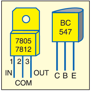
When power is switched on, LED1 glows to indicate the presence of power in the circuit and LED2 glows to indicate the presence of RFID reader. Simultaneously, the ‘Automatic RFID Car Parking’ message is displayed on LCD1 along with a short beep from piezobuzzer PZ1. Transistor BC547 drives the buzzer. Pin details of 7805, 7812 and BC547 are shown in Fig. 6.
When a car crosses the IR LED1-D1 pair installed at the entry gate, the gate boomer does not open until an RFID tag is placed near the RFID reader. After the tag is placed near the reader, the gate boomer opens for three seconds and closes automatically. If the initial recharge amount was Rs 900, the LCD display shows ‘Vehicle1 Amount’ in the first line and ‘Deducted 100’ in the second line, followed by ‘Balance Amount’ in the first line and ‘800’ in the second line. It is then followed by display of ‘Number of Cars’ in the first line and ‘001’ in the second line. If the parking lot is full, the message “Parking is Full, Sorry for Inconvenience” is displayed on LCD1.
When a car leaves the parking area and crosses the IR beam between IR LED2 and D2 at the exit gate, the vehicle count decreases by one. The LCD shows the number of cars in the parking lot along with “Thanks for Visiting” message.

Software
The program (parking.c) for the microcontroller is written in C and compiled using Keil software to generate the hex code. The program coding starts with ‘#include’ and ‘#include’ header files. The microcontroller port pins are defined using ‘sbit’ function for interfacing with the surrounding peripherals. The entry gate motor is controlled using ‘sbit START_POINT=P1^3;’ code.
The LCD is initialised using the following code:
[stextbox id=”grey”]void lcdinit(void)
{
lcdcmd(0x38);
DelayMs(250);
lcdcmd(0x0E);
DelayMs(250);
lcdcmd(0x01);
DelayMs(250);
lcdcmd(0x06);
DelayMs(250);
lcdcmd(0x80);
DelayMs(250);
}[/stextbox]
Construction and testing
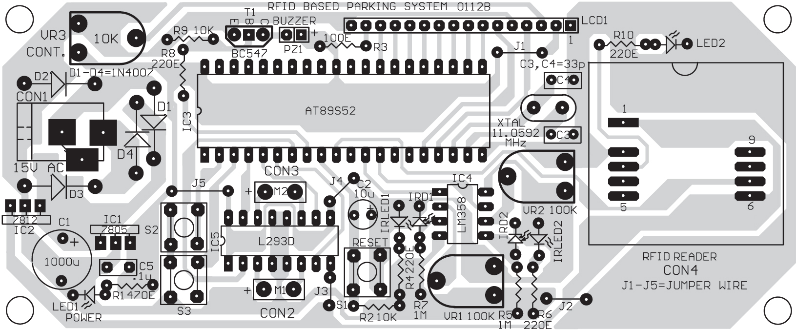
A single side PCB layout for the RFID based automatic vehicle parking system is shown in Fig. 7 and its component layout in Fig. 8. Burn the hex code into the AT89S52 microcontroller using a suitable programmer and then mount the microcontroller on the PCB. Install IR LED1-D1 pair at the entry gate such that these face each other. Similarly, install IR LED2-D2 pair at the exit gate.
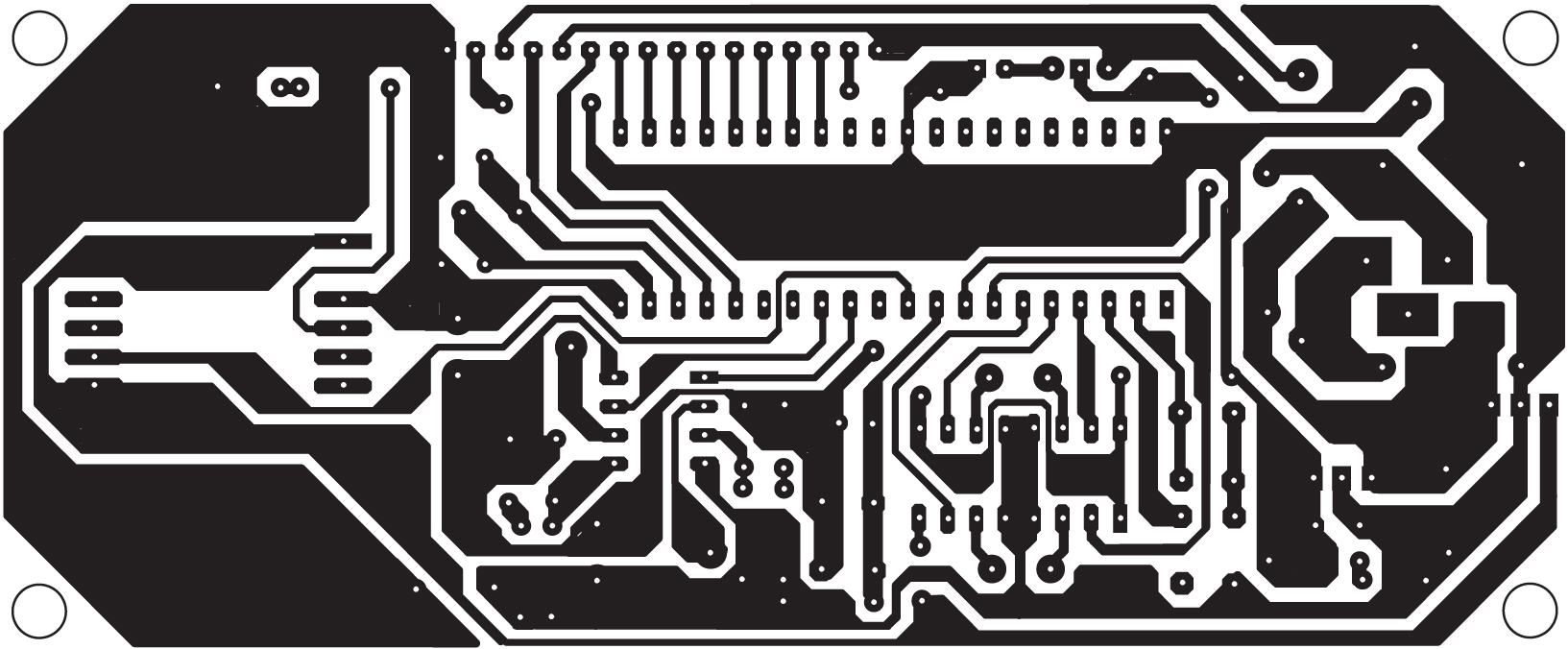
Download PCB and component layout PDFs: click here
For testing, switch on the circuit, interrupt the infrared beam between IR LED1 and IR D1 with your hand or some other opaque object and then remove it, and place the tag near the reader. The LCD should show the message as described earlier in ‘How this vehicle parking system works’ section. An amount of Rs 100 should be deducted for every interruption of the IR beam. The card can be recharged by pressing the pushbutton switches (S2 and S3) provided in the circuit. Pressing switch S2 recharges the card with Rs 900 and pressing switch S3 recharges it with Rs 500.
Similarly, interrupt the IR beam at the exit gate. LCD1 should show the number of cars in the parking lot along with ‘Thanks for Visit’ message. No amount should be deducted at the time of exit.
Download source code: click here
Feel interested? Check out other circuit projects in the circuit section.

can you please upload the source code please…
Dear maniyankal, the source code is provided within the article.
dear abhimanyu i tried the source code link but its showing page cannot be opened
Could you please check now? I have updated the link.
can i buy this project from efy?
cross questions requried regarding car parking sysytem like is there blockage of frequency??….due to some regions!!!!…….
Where to place RFID reader?Below the car as the RFID card detect it or somewhere else?
no we use rfid card like our other cards
We want to install RFID card system barrier gate of entry and exit of cars in our residential apartments in Gurgaon
Please guide us and submit quote
can I implement this with Arduino?
sir make as you above describe this project but its not working
Kindly elaborate your query.
Can you let me know about the rfid reader..like is it ttl or DB-9 socket one?
can you please upload the source code
can u pls upload the code
Hi, the source code is present on the 3rd page of the article.
may i know what programming language should i use to create something similar to this?
This project uses C programming language but you can also use other programming language including Python language.
Hello can you tell me how much expense on RFID car parking system, please
sir can u mail me the code of smart car parking system.
sir can u mail me the code of smart car parking system.
Looking for RFID based car parking systems for basement parking in condominium
You can try Arduino based RFID based automatic car parking system project available on our website at https://kitsnspares.com/. The complete kit also available