


 An audio signal can be used as a form of input to control any security system. For example, an automatic security camera can be configured to respond to a knock on the door. The security system switcher circuit described here allows the security system to automatic in on state. It uses a transducer to detect intruders and a 5V regulated DC power supply provides power to the circuit.
Security system switcher circuit
As shown in Fig. 1, a condenser microphone is connected to the input of small signal pre-amplifier built around transistor T1. Biasing resistor R1 determines to a large extent the microphone sensitivity. A microphone usually has an internal FET which requires a bias voltage to operate. The sound picked up by the microphone is amplified and fed to input pin 2 of IC1 (LMC555) wired in monostable configuration.
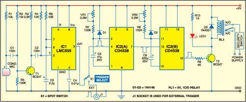
IC2 (CD4538B) is a dual, precision monostable multivibrator with independent trigger and reset controls. The output of IC1 is connected to the first trigger input pin 4 of IC2(A) through switch S1. If an intruder opens or breaks the door, IC1 is triggered by sound signals; the timer output pin 3 of IC1 goes high and enables first monostable multivibrator IC2(A). IC2(A) provides a time period of around 5 to 125 seconds, which is adjusted with preset VR1.

Another monostable multivibrator IC2(B) also provides a time period of around 25 to 600 seconds, which is adjusted with preset VR2. The output of IC2(B) is used to energise relay RL1. Indicator LED1 is provided to display the relay activity. Any AC/DC operated security gadget is activated or deactivated through a security switch. Thus, the security switch of the gadget is connected in the n/o contacts of the relay.You can also operate high power beacons, sirens or hooters in place of the security switch for any AC/DC operated security gadget.
Construction & testing
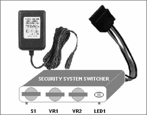
Assemble the circuit on a general purpose PCB and enclose it in a cabinet as shown in Fig. 2 along with 5V adaptor for powering the circuit. Connect the security switch according to the circuit diagram and use appropriate AC/DC power supply required to operate the security gadget.

Warning! All relevant electrical safety precautions should be taken when connecting mains power supply to the relay contacts. With the help of single pole double throw (SPDT) switch S1, internal or external trigger input (active high signal) can be selected.
The article was first published in January 2007 and has recently been updated.
