


This project suggests a solar powered home lighting system that uses solar power and LED lighting technology in a more efficient way. Solar power systems use solar panels to convert the sun’s energy directly to electricity. This electricity is stored in the batteries that can supply only DC output. All available lighting systems, including LED lights, work on AC power. So the DC supply needs to be converted to AC using inverters, which causes some loss of power. The amount of power lost during this process depends on the efficiency of the inverter.
But, if we look closely, in most of the LED lighting systems, the AC is converted back to DC using switched-mode power supplies (SMPS) having an efficiency of around 80 per cent.
This system proposes to use the power from the battery directly for LED lighting, eliminating the need for DC-to-AC conversion by the inverter and AC-to-DC conversion by the LED light’s SMPS supply.Many companies are coming up with drivers for brushless DC motor-based fans that run directly on battery supply. So this system can be used for such fans as well. In this way, one can save on the cost of an inverter and make lighting and fan systems more efficient and eco-friendly.

The system has two batteries. When both the batteries are charged, load is connected to the first battery (BATT.1) by default. If this battery’s voltage goes below the defined level, the load shifts to the second battery and the first battery starts charging. Similarly, when the second battery gets discharged, the load is shifted back to the first battery and the second battery starts charging. The system also monitors solar voltage. If the voltage is not sufficient for charging, the battery gets charged through the battery charger driven by AC mains.
Solar powered home lighting system circuit
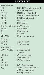
Fig. 1 shows the circuit of the solar powered home lighting system. The circuit is built around microcontroller PIC16F877A (IC1), two 80W solar panels (connected in parallel at CON1), two 12V, 80Ah batteries (BATT.1 and BATT.2) and a 16×2 LCD. A separate 12V battery charger (connected at CON2) is used to charge the batteries when solar voltage is not sufficient. The LED lights made using 12V LED strips available off-the-shelf can be connected in parallel at CON3.

PIC16F877A is a low-power, high-performance, CMOS 8-bit microcontroller. Its main features are 8kB Flash, 256 bytes of EEPROM, 368 bytes of RAM, 33 input/output (I/O) pins, 10-bit 8-channel analogue-to-digital converter (ADC), three timers and a watchdog timer with its own on-chip crystal oscillator for reliable operation.
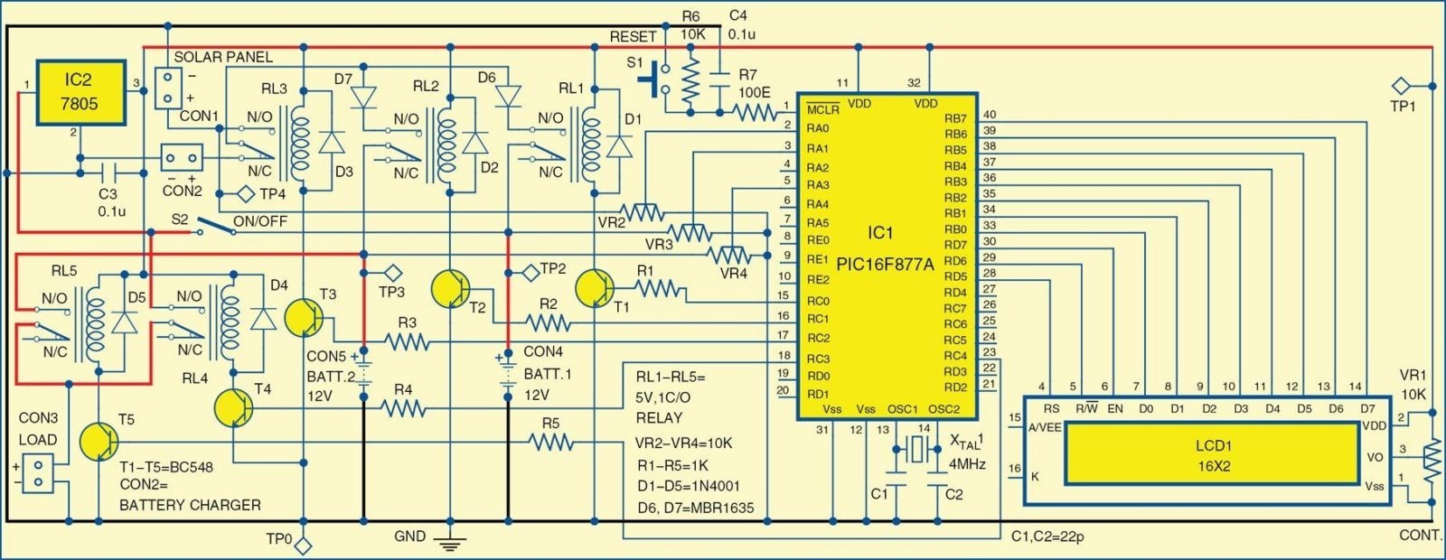
Port pins RB0 through RB7 of IC1 are connected to pins D0 through D7 of LCD1. Port pins RD5 through RD7 of IC1 are connected to RS, R/W and EN of LCD1, respectively. Preset VR1 is used for contrast control of the LCD. The LCD shows information about which battery is charging and the source used. ADC channels RA0, RA1 and RA3 of IC1 monitor the voltage levels of solar panel, BATT.1 and BATT.2, respectively. Presets VR2, VR3 and VR4 are used so that the voltage levels never exceed 5V. Microcontroller IC1 converts these analogue levels into digital form and controls the overall process.
Port pins RC0 and RC1 of IC1 are used to drive relays RL1 and RL2 to select the battery to be charged. If both the batteries are fully charged, BATT.1 gets connected to the load by default. Once this battery gets discharged, the load gets switched to BATT.2 and BATT.1 starts charging.
The source of charging (solar or battery charger) is selected through relay RL3. If the solar voltage is sufficient for charging, port pin RC2 drives relay RL3 to connect the solar charging system to the battery, otherwise it is connected to the battery charger. The battery connected to the load is selected using relays RL4 and RL5 that are driven through port pins RC3 and RC4.
The power supply for the microcontroller is always delivered through BATT.1 after proper regulation. Switch S2 is used to turn on/off the system. A 4MHz crystal is connected to pins 13 and 14 of microcontroller IC1 to provide the basic clock frequency. Power-on reset is provided by the combination of resistor R6 and capacitor C4. Switch S1 is used for manually resetting the microcontroller. Diodes D1 through D5 act as freewheeling diodes.
Software
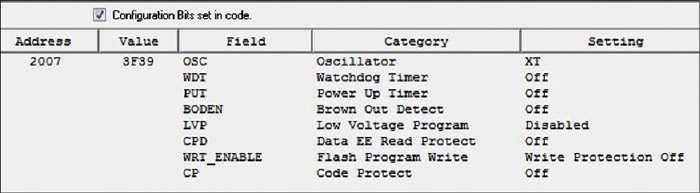
The program is written in ‘C’ language and compiled using HI-TECH C compiler along with MPLAB to generate the hex code. The generated hex code is burnt into the microcontroller using a suitable programmer with configuration bit settings. The configuration bits are shown in Fig. 2. The program is easy to understand.
Download the PCB and Component Layout PDF: Click Here
Download Source Code: Click Here
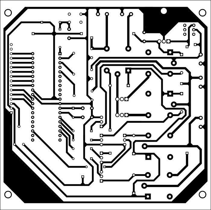
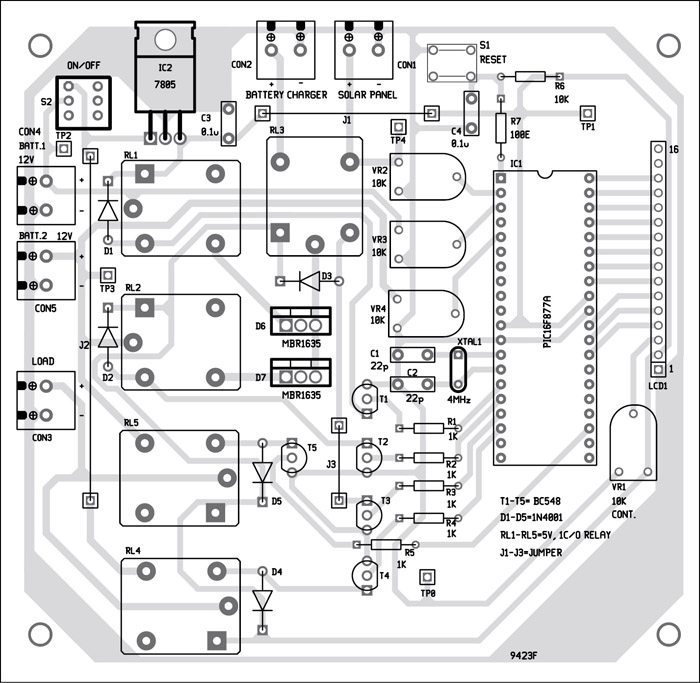
A single side PCB for the solar powered home lighting system is shown in Fig. 3 and its component layout in Fig. 4. Assemble the circuit on the provided PCB to save time and minimise any assembly errors. Use IC base for microcontroller IC1. Set VR2, VR3 and VR4 as follows:
- Connect 20V stable external supply at CON1 and adjust VR2 such that you get 5V at pin 2 of microcontroller IC1.
- Connect 15V stable external supply at CON4 and CON5, and adjust VR3 and VR4 such that you get 5V at pins 3 and 5 of IC1. Remove the supplies after setting the potmeters and seal their positions with glue.
Connect two 80W solar panels in parallel to CON1 and an off-the-shelf available 12V battery charger to CON2. Connect two 12V, 80Ah batteries at CON4 and CON5. You can use 12V, 150Ah batteries for better backup, but this will increase the charging time. You need to select the maximum load in such a way that the duration of discharge for the active battery is more than the charging time for the other.
Take 12V LED strips from market to build the LED lights. You can connect strips in parallel to increase the lumens. But ensure that the overall wattage of all the lights is less than the maximum calculated load as mentioned above.
Build these lights with suitable reflector and diffuser, otherwise the light from the LEDs will be focussed and not so pleasant. Connect these LED lights in parallel to CON3.
Switch on the system and you will see ‘solar charger’ message displayed on the first line of the LCD. The LCD will show ‘BATT-1 FULL’ and ‘BATT-2 CHARGING’ to indicate that BATT.1 is delivering power to load and BATT.2 is charging, and vice versa. The LCD display will also indicate the source of charging as ‘SOL.’ for solar and ‘AC’ for battery charger.
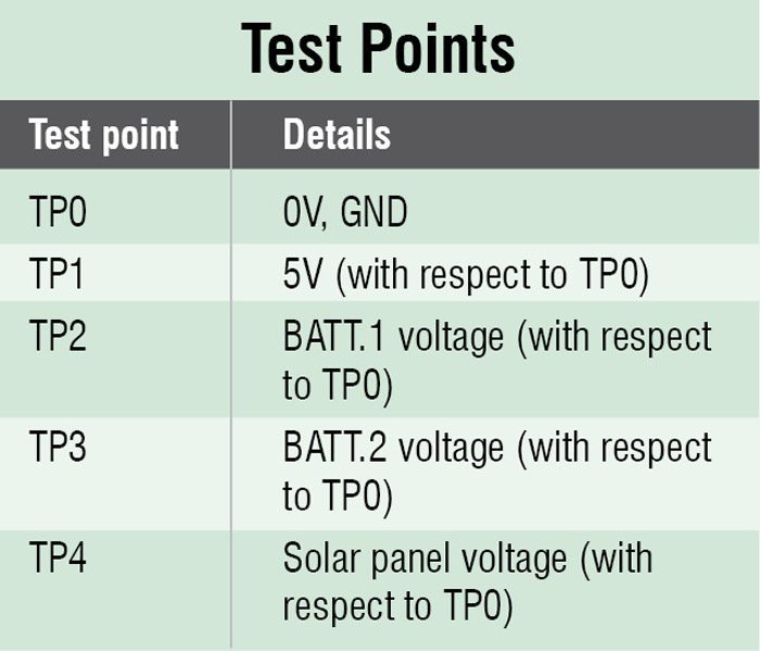
To test the circuit for proper functioning, verify 5V power supply at TP1, battery voltages at TP2 and TP3 and solar panel voltage at TP4. All voltages are measured with respect to TP0.
Feel interested? Check out more solar electronics projects you can build at home.

can use 12v 7.5 ah battery and 8w solar panel for sutable
do you have circuit layout using software?
Kindly elaborate your query.
do you have circuit in proteus format
no
is there over charge and deep discharge protection is there
having issue circuit . who can help to advice on this?
Kindly elaborate your query.
ok
Call me @ +91-94800 51739 – have a simple solution to this. I have CC which does all of this work using one chip and is cost effective upto 150W systems. willing to support on OEM basis.
@kiran please can we chat on whatsapp +2348122020148 on the particular issue.
Kindly elaborate your query.
Dear kiran please mail me on [email protected] about charging circuit details. I am interested in this my mobile no is 9422368409 at pune. If you call me between 10.30 t0 05.00 it will be convenient for me because sometimes my mobile goes out of range. Thans a lot.
Does this project require any coding?
Yes, this project requires coding, You can get the source code from the second page.
can i have the source code for this project..i can’t find it
and also flow chart if possible
You can download the source code from here.
hello can you share details of solar lighting panel for street light with led light on same case assembley.
i required few things
1. single line diagram
2. drawing
3. and detailed component list with there ratings
Hello
This is an amazing idea and I want to pursue it as my minor project. I’m an electrical engineering student. Can I please get some references or detailed elaboration for the same so that I can implement it successfully.
can use 12v 17 Ah ah battery and 30w solar Panel , Di in need to change something in the circuit
Hi, Thanks for these details.
Do you have any load calculation means how much arrey current how many LEDs with wattage we can connect to this circuit.
Hi all Master, Source Code cant download
Thank You
Cheers
Jacky
Please refresh the page.
Could you please share the Gerber file of the PCB and Component Layout?