
 Pulse-width modulation (PWM) or duty-cycle variation methods are commonly used in speed control of DC motors. The duty cycle is defined as the percentage of digital ‘high’ to digital ‘low’ plus digital ‘high’ pulse-width during a PWM period. Fig. 1 shows the 5V pulses with 0% through 50% duty cycle.
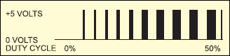
The average DC voltage value for 0% duty cycle is zero; with 25% duty cycle the average value is 1.25V (25% of 5V). With a 50% duty cycle the average value is 2.5V, and if the duty cycle is 75%, the average voltage is 3.75V and so on. The maximum duty cycle can be 100%, which is equivalent to a DC waveform. Thus by varying the pulse-width, we can vary the average voltage across a DC motor and hence its speed.
Circuit Diagram
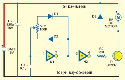
The circuit of a simple speed controller for a mini DC motor, such as that used in tape recorders and toys, is shown in Fig. 2.
Circuit Explanation:
Here N1 inverting Schmitt trigger is configured as an astable multivibrator with a constant period but variable duty cycle. Although the total in-circuit resistance of VR1 during a complete cycle is 100 kilo-ohms, the part used during positive and negative periods of each cycle can be varied by changing the position of its wiper contact to obtain variable pulse-width. Schmitt gate N2 simply acts as a buffer/driver to drive transistor T1 during positive incursions at its base. Thus the average amplitude of DC drive pulses or the speed of motor M is proportional to the setting of the wiper position of VR1 potmeter. Capacitor C2 serves as a storage capacitor to provide stable voltage to the circuit.
Thus, by varying VR1 the duty cycle can be changed from 0% to 100% and the speed of the motor from ‘stopped’ condition to ‘full speed’ in an even and continuous way. The diodes effectively provide different timing resistor values during charging and discharging of timing capacitor C1.


The pulse or rest period is approximately given by the following equation: Pulse or Rest period ≈ 0.4 x C1 (Farad) x VR1 (ohm) seconds. Here, use the in-circuit value of VR1 during pulse or rest period as applicable.
The frequency will remain constant and is given by the equation:
Frequency ≈ 2.466/(VR1.C1) ≈ 250 Hz (for VR1=100 kilo-ohms and C1=0.1 µF)
The recommended value of in-circuit resistance should be greater than 50 kilo-ohms but less than 2 mega-ohms, while the capacitor value should be greater than 100 pF but less than 1 µF.

More interesting projects available here.


???
Would the schematic above ( Fig 2: DC Motor speed control using PWM method ) handle 9V without modifications?
Should be fine. 4000 series CMOS is good for 15V. As the logic input thresholds scale with the supply voltage the control should work as well. 9V may be a bit much for a 6V motor. An extra resistor can limit the PWM duty cycle to compensate.