
 In most houses, water is first stored in an underground tank (UGT) and from there it is pumped up to the overhead tank (OHT) located on the roof. People generally switch on the pump when their taps go dry and switch off the pump when the overhead tank starts overflowing. This results in the unnecessary wastage and sometimes non-availability of water in the case of emergency. This water-level controller circuit makes this system automatic. It switches on the pump when the water level in the overhead tank goes low and switches it off as soon as the water level reaches a pre-determined level. It also prevents ‘dry run’ of the pump in case water level in underground tank goes below suction level.
We have one more automatic water level controller circuit that can be useful too.
In this water-level controller circuit, the common probes connecting the underground tank and the overhead tank to +9V supply are marked ‘C’. The other probe in underground tank, which is slightly above the ‘dry run’ level, is marked ‘S’. The low-level and high-level probes in the overhead tank are marked ‘L’ and ‘H’, respectively.
Water-level controller circuit
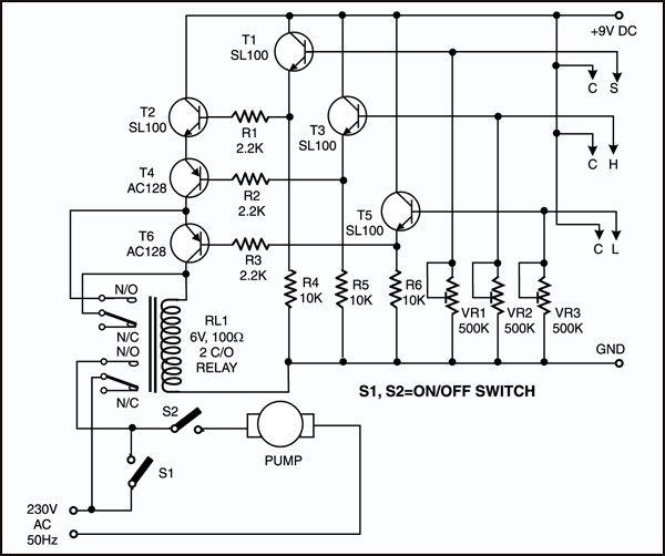
When there is enough water in the underground tank, probes C and S are connected through water. As a result, transistor T1 gets forward biased and starts conducting. This, in turn, switches transistor T2 on. Initially, when the overhead tank is empty, transistors T3 and T5 are in cut-off state and hence pnp transistors T4 and T6 get forward biased via resistors R5 and R6, respectively.
As all series connected transistors T2, T4, and T6 are forward biased, they conduct to energize relay RL1 (which is also connected in series with transistors T2, T4, and T6). Thus the supply to the pump motor gets completed via the lower set of relay contacts (assuming that switch S2 is on) and the pump starts filling the overhead tank.

Once the relay has energised, transistor T6 is bypassed via the upper set of contacts of the relay. As soon as the water level touches probe L in the overhead tank, transistor T5 gets forward biased and starts conducting. This, in turn, reverse biases transistor T6, which then cuts off. But since transistor T6 is bypassed through the relay contacts, the pump continues to run. The level of water continues to rise.
Circuit Operation
When the water level touches probe H, transistor T3 gets forward biased and starts conducting. This causes reverse biasing of transistor T4 and it gets cut off. As a result, the relay de-energises and the pump stops. Transistors T4 and T6 will be turned on again only when the water level drops below the position of L probe.
Presets VR1, VR2, and VR3 are to be adjusted in such a way that transistors T1, T3, and T5 are turned on when the water level touches probe pairs C-S, C-H, and C-L, respectively. Resistor R4 ensures that transistor T2 is ‘off’ in the absence of any base voltage. Similarly, resistors R5 and R6 ensure that transistors T4 and T6 are ‘on’ in the absence of any base voltage. Switches S1 and S2 can T4 and T6 are ‘on’ in the absence of any base voltage. Switches S1 and S2 can be used to switch on and switch off, respectively, the pump manually.

Project Installation
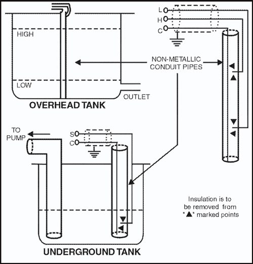
You can make and install probes on your own as per the requirement and facilities available. However, we are describing here how the probes were made for this prototype.
The author used a piece of nonmetallic conduit pipe (generally used for domestic wiring) slightly longer than the depth of the overhead tank. The common wire C goes up to the end of the pipe through the conduit. The wire for probes L and H goes along with the conduit from the outside and enters the conduit through two small holes bored into it as shown above.
Care has to be taken to ensure that probes H and L do not touch wire C directly. Insulation of wires is to be removed from the points shown. The same arrangement can be followed for the underground tank also. To avoid any false triggering due to interference, a shielded wire may be used.
More interesting projects available here.

please share pcb layout
what is the pump range
what is replace value for AC 128 Transister?
not available in markets.
AC 128 Transistor are not available in markets.
can i used bc337 transistor instead of AC 128