


Nowadays numerous electronic devices make use of vibrotactile feedback to increase user interaction with the help of suitable haptic feedback hardware like the eccentric rotating mass motors, linear resonant actuators, and piezoelectric actuators.
The most popular type of eccentric rotating mass (ERM) motor inside of consumer electronic devices is the pancake vibration motor (coin vibration motors).
Pancake motors are used cosmically in cell phones, healthcare/medical devices, wearables, video game controllers, and sex toys to inexpensively provide a perceptible vibration to the user.

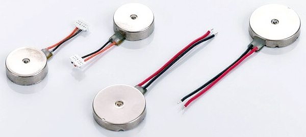
Pancake Vibration Motor
Pancake vibration motors are compact and very convenient to use because they have no external moving parts, and just can be affixed in place with the pre-attached adhesive sticker on the back of it.

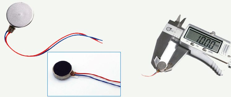
In principle, pancake vibration motors use the same operating principle as eccentric rotating mass motors (also known as pager motors), however their eccentric mass is kept in their small circular body having diameter ranges from Ø7mm to Ø14mm. This low-profile construction technique makes them very popular in many space-restricted applications.
The standard (brushed) coin vibration motors are constructed from a flat printed circuit board on which the 3-pole commutation circuit is laid out around an internal shaft in the centre. The required operating voltage is usually about 3V, and the current consumption is around 60mA. It should be noted that pancake vibration motors require a relatively high start voltage, compared to other vibration motors, which must be considered in designs.
Typically, this voltage is around 2.3V, and failure to follow this could result in starting trouble when it is lying especially in vertical orientation. This is because, in vertical orientation the motor must force the eccentric mass over the top of the shaft on initial cycle.
Driver Circuitry
The simplest way to drive a pancake motor is directly from a power source such as a a battery. This is the simplest connection method and commonly used for vibrating alert applications that require just an on/off vibration. For advanced applications, pulse width modulation (PWM) technology can be used along with dedicated (haptic feedback) pancake motor driver chips, or with driver electronics based on discrete components.
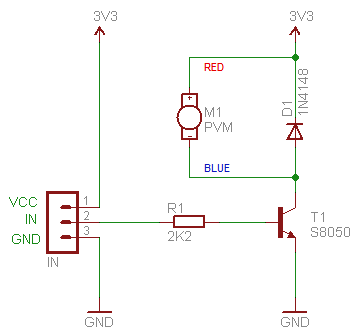
This PWM method is now very common and is an extremely cost-effective way to vary the vibration amplitude of a vibration motor with a microcontroller. Shown below is a tried and tested pancake vibration motor driver circuit which accepts a simple on/off GPIO signal, as well a PWM input from a microcontroller.
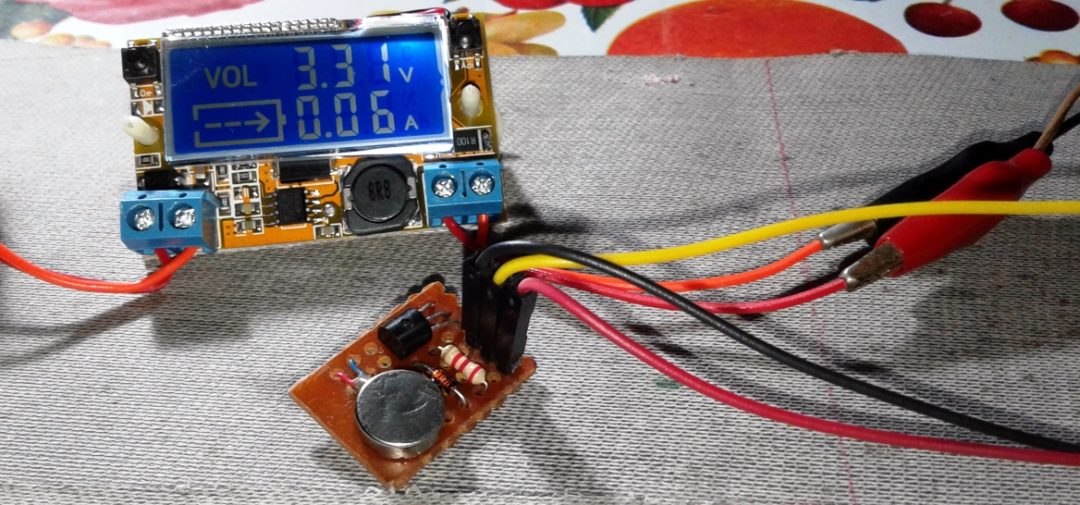
Prototype of my pancake motor driver wired on a piece of perfboard is shown below:
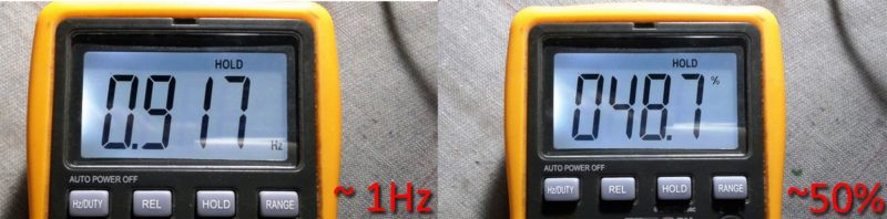
Following is a quick video of the initial try out of this circuit, driven by a square wave of about 1Hz (with near 50% duty cycle) from a 555 IC-based pulse generator module (bought from eBay). Watch it (you’ll need sound to hear the motor going).
Using Pancake Vibration Motors with Arduino
In case you don’t have access to any pulse generators, you can use your Arduino for experimenting with this driver circuit. Just ‘copy-paste-compile-upload’ the included sketch and take output from pin 13 (D13) of the Arduino. Needless to say, using some more better code you can make amazing haptic feedback/vibrator projects/devices. I would love to hear how it works for you – let me know in the comments!
In the code, each time the digitalWrite function is used, it needs to be followed with the delay function. Here the duty cycle is 50%, and the frequency is 1Hz. To get a desired duty cycle, do the math:
“Duty Cycle (%) = 100 x delay time HIGH/delay time LOW + delay time HIGH”. The frequency (inverse of the period) can also be changed by changing the value of total time that takes for one cycle, ie. the period.
/*
*Pancake Vibration Motor Test Code
*Turns on the motor on for half second, then off for half second, repeatedly.
*Connect output pin D13 of Arduino to the pancake driver circuit’s input terminal.
*Refer the schematic to proceed.
*This is an example code for basic test.
*Prepared by T.K.Hareendran.
*/
void setup() {
pinMode(13, OUTPUT);// Initialize D13 as an output pin
}
// Drive the motor with 1Hz square wave @ 50% Duty Cycle
// See the “Maths” included in the article
void loop() {
digitalWrite(13, HIGH); // turn the drive on (HIGH)
delay(500); // wait for 500ms period
digitalWrite(13, LOW); // turn the drive off (LOW)
delay(500); // wait for 500ms second period
}
//End of Code

you forget to mention one pic to show how we connect fisicaly in arduine de motor