


 This simple linear timer can be used to control any electrical appliance that needs to be switched off after a certain time, like a small heater or a boiler, provided the relay-switch parameters meet the requirements of that appliance. It uses low-cost components and combines digital precision with simple analogue control. This provides long timing durations without the use of high-valued resistors or capacitors.
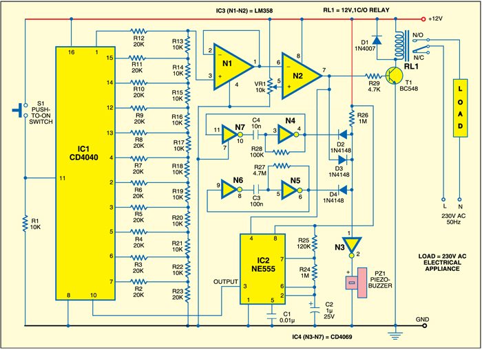
A linear timer circuit
The circuit is built around CD4040, LM358, CD4069 and NE555. The working of the timer is quite simple, based on digital-to-analogue conversion (DAC). The counter (CD4040) runs the DAC (formed by R-2R ladder resistors R2-R23 and following operational amplifier IC3 (N1 and N2)). The second op-amp (N2) compares the DAC output with a variable voltage set by VR1 according to the time requirement. The larger the voltage set, the longer the time duration and higher the count, larger the DAC output voltage and vice versa.
Circuit operation
As soon as the count of the counter becomes large enough to produce slightly larger voltage than the voltage set by potentiometer VR1, the second op-amp (N2) goes low to cut-off transistor T1 and reset the clock generator built around NE555 (IC2). The clock generator thus produces no further pulses and the counter remains static at this particular count indefinitely.

Pressing the reset switch (S1) resets the counter (IC1). Thus the voltage from the DAC falls to zero causing the second op-amp (N2) to go high, enabling clock generator IC2 and making transistor T1 conduct. The timer again activates and simultaneously the relay energises.
A diode is used in parallel with the relay coil to suppress the reverse induced voltage. The maximum timing achievable is dependent on the frequency of the clock generator and the supply voltage:

This happens because the ratio Vopmax/V is a slow function of supply voltage. Vopmax increases with increase in V, so this ratio varies slowly with supply voltage and can be assumed to be constant.
So for f=1 Hz and supply voltage V=15 volts, the maximum achievable timing is 3686 seconds, which is slightly more than one hour. 555 timers can easily generate frequencies as low as 0.1 Hz. The timer can also withstand fluctuations in the supply voltage.
In this circuit, at 12V, resistors R24, R25 and capacitor C2 produce around 1.47Hz frequency and the relay de-energises after around 1.5 hours to switch off the load. At the same time, the alarm built around IC4 sounds indicating that the appliance is off. Assemble the circuit on a general-purpose PCB.
EFY note
Add two resistors to the potentiometer—one at the ground and the other at the positive supply—for minimum and maximum timing. Vary VR1 between 0 and VOPmax such that the op-amp output doesn’t exceed the supply voltage (VOPmax = V-1.5).
The project was first published in September 2010 and has recently been updated.

please upload the part list
Is it possible to get the PCB along with the parts?