


Here is a simple water overflow alarm circuit to prevent overflow of water from overhead tanks. The circuit can be implemented to fit other applications as well that require liquid level measurement. It is built around two BC547 transistors (T1 and T2) and two timer 555 ICs (IC1 and IC2). Both IC1 and IC2 are wired in astable multivibrator mode. Timer IC1 produces low frequency, while timer IC2 produces a high frequency. As a result, a beeping tone is generated when the liquid tank is full.
Water overflow alarm circuit
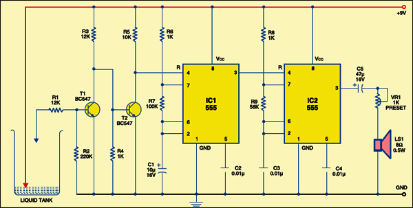
Circuit operation
Initially, when the tank is empty, transistor T1 does not conduct. Consequently, transistor T2 conducts and pin 4 of IC1 is low. This low voltage disables IC1 and it does not oscillate. The low output of IC1 disables IC2 and it does not oscillate. As a result, no sound is heard from the speaker.
But when the tank gets filled up, transistor T1 conducts. Consequently, transistor T2 is cut off and pin 4 of IC1 becomes high. This high voltage enables IC1 and it oscillates to produce low frequencies at pin 3. This low-frequency output enables IC2 and it also oscillates to produce high frequencies. As a result, a sound is produced by the speaker. Using preset VR1 you can control the volume of the sound from the speaker.

Construction & testing
The circuit can be powered from a 9V battery or from mains by using a 9V power adaptor. Assemble the circuit on a general-purpose PCB and enclose in a suitable cabinet. Install two water-level probes using metal strips such that one touches the bottom of the tank and the other touches the maximum level of the water in the tank. Interconnect the sensor and the circuit using a flexible wire.
The project was first published in July 2009 and has recently been updated.
Thank you very much for the project. I made it and it worked very well. But which parameters can I measure and vary ?
Thanks for the feedback! You can check the oscillation frequencies at pin 3 of both the IC1 and 1C2 when the water is empty as well as full. Also you can vary VR1 to control the volume of the alarm sound.
I have one question if tank got fulled the water level remain same for a hour or 1/2 hour then the alarm will rang until water level goes some inch down
This circuit is not an automatic system and so you have to manually switch off the alarm sound once the tank is full. That is, if water tank is full, you need to switch off the circuit as well as the motor pump.
You used two ICs and two tansistors in this circuit. Can we make this use one IC and one transistor?
My alarm is not alarming after sensor touched by water. When i switched off and then on the alarm it started alarming!!! Why this is happening?
When you touch the sensor to 5V, collector of T1 should be low and collector of T3 should be high. If they are not, check proper connections of transistors T1 and T2 or try replacing them. Also check proper connections of IC1 and IC2