


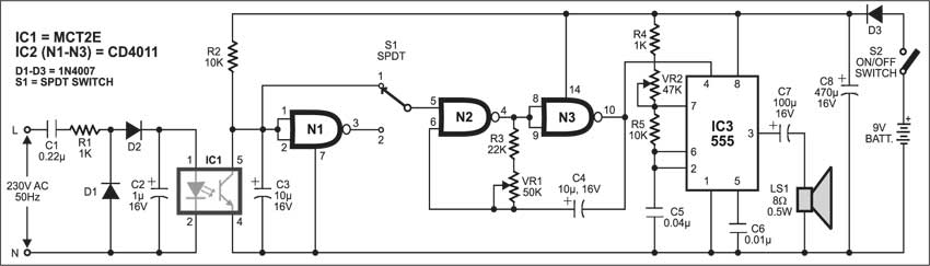
 This mains indicator sounds an alarm whenever AC mains fails or resumes. It is very useful in industrial installations, cinema halls, hospitals, etc. The mains detector circuit is built around capacitors C1 and C2, resistor R1, and diodes D1 and D2. It provides sufficient voltage for the glowing of internal LED of optocoupler MCT2E (IC1).
Mains Indicator Alarm Circuit
Initially SPDT switch S1 is at position 1. When mains fails, pin 5 of gate N2 goes high and the oscillator built around gates N2 and N3 of IC2 produces low-frequency oscillations at pin 10, which are further given to pin 4 of IC 555 (IC3). The oscillation frequency can be varied from 0.662 Hz to 1.855 kHz using preset VR1.
IC 555 (IC3) is wired as an audio tone generator. The tone of this audio oscillator can be varied from 472 Hz to 1.555 kHz using preset VR2. The low-frequency input activates IC3 to generate audio tones and loudspeaker LS1 connected to its output pin 3 sounds an alarm indicating mains failure.

Circuit operation
To turn off the alarm, slide the pole of switch S1 to position 2. Now the circuit is ready for sensing the mains resumption.
When mains resumes, pin 5 of gate N2 goes high and the oscillator built around gates N2 and N3 of IC2 produces low-frequency oscillations at pin 10, which are given to reset pin 4 of IC3. As a result, loudspeaker LS1 again sounds to indicate that mains has resumed. To turn off the alarm, slide the pole of switch S1 back to position 1. Now the circuit is again ready for sensing the mains failure.
The circuit works off a 9V battery. It can be housed in a box and installed where you want to monitor the status of mains.
The article was first published in November 2004 and has recently been updated.
pcb layout please