
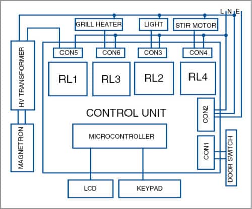
 This project is designed to replace the defective control board with a new Control Board in Microwave Oven irrespective of brand and capacity. Microwave ovens are dumped as e-waste due to unserviceable control boards. Spare parts such as magnetron, HV transformer, HV diode and drive mechanism, except control board, are readily available in the market. Block diagram of the microwave oven is shown in Fig. 1
Circuit and working
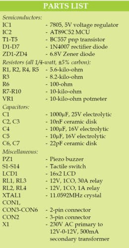
The circuit diagram of the microwave oven is shown in Fig. 2. It is built around 5V voltage regulator 7805 (IC1), microcontroller (MCU) AT89C52 (IC2), four 12V relays (RL1 through RL4), five pnp transistors (BC557), 14 tactile switches, one 16×2 line LCD (LCD1) and a few discrete components.
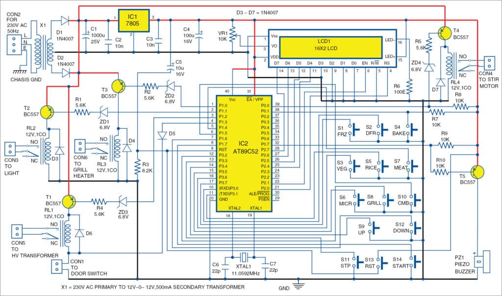
The circuit is powered with 230V AC. Transformer X1 reduces voltage to 12 volts. Diodes D1 and D2 act as rectifier diodes. Capacitor C1 is connected as a filter. The rectified, filtered and regulated DC voltage is fed to the power section of the circuit, and 5V is fed to the control circuit via 7805.
AT89C52 MCU, running at a clock frequency of 11.0592MHz, is interfaced with 14 controlling switches, 16×2 LCD and four relays. Use Zener diodes ZD1 through ZD4 to connect 12V relay through a pnp transistor to 5V MCU. Diode D5 prevents the 12V supply to the MCU when the door switch is opened.

Relays RL1, RL2, RL3 and RL4 are connected to the MCU through four relay driver transistors T1, T2, T3 and T4, respectively. Transistor T5 is used to drive the piezo buzzer. Pnp transistors are used as active low output from the controller. The LCD is connected at port P2. Potmeter VR1 can be used to adjust the contrast of LCD1. D4 through D7 are protection diodes for relay driver transistors. AT89C52 runs with a crystal frequency of 11.0592MHz.
Software
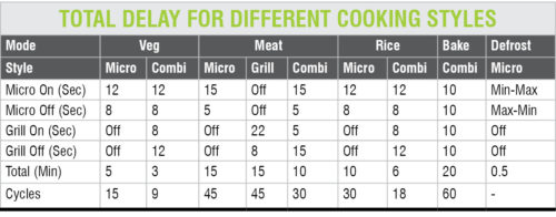
The software is written in C language and compiled with Kiel µvision 4 software. Logic behind the software is described briefly for easy understanding and editing. In the main part of the software, the MCU scans continuously the condition of the seven input switches, comprising vegetable (VEG), meat, rice, frozen (FRZ), bake, up and defrost (DFR). If any these switches are found de-pressed by the program, the software jumps to the corresponding sub-routine. On auto sub-routine, each branch sets the total time of cooking and on/off delay timing for magnetron and grill heater. Total delay and on/off delay against each cooking styles are shown in the table.

On de-pressing Defrost, the program executes defrost sub-routine. Defrosting technique provided in the microwave oven is for cooking or heating refrigerated food. Normal cooking of refrigerated food in an oven results in rapid burning of outer parts, resulting in damaged food.
For compensating this at defrost mode, the system initially switches on the magnetron just for a few seconds. It slowly increases on time and decreases off time. This technique helps penetrate the heat throughout the food evenly.
Grill option is provided for meat only. Combi option is provided for rice, meat and cake only. On de-pressing Up, the software executes manual mode sub-routine. At manual mode, total cooking time can be selected by pressing Up or Down. With each press, time increments or decrements by one second.
By holding Up or Down, time increments or decrements by 10 seconds. After setting the time, any cook mode can be selected (Micro Veg or Combi). On/off delay is according to the preset sequence, according to the type of cooking selected. Accurate delay time is achieved by enabling Timer0 of the MCU (IC2).
Unlike in conventional ovens, double protection is provided for door opening while cooking, both in software and hardware. When the door is opened, coil ground connection to magnetron relay disconnects. At the same time, software detects this condition and switches off the magnetron.
LCD1 shows all parameters. It is connected in four-wire method or 4-bit mode of operation. Corresponding software is simple and self explanatory.
At EFY Lab, Topview programmer was used for programming the IC.
Download Source Code
Construction and testing
A PCB layout of the microwave oven is shown in Fig. 3 and its components layout in Fig. 4.
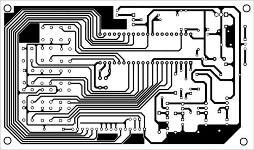
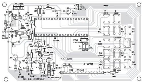
Download PCB and Component Layout PDFs: click here
Place all components on the PCB and solder carefully. Load the program (hex file) of the software to the MCU IC. Use IC base on the PCB. Solder the tactile switches on a separate PCB and connect the same to the main PCB, as per the circuit diagram.
After assembling the circuit, enclose it in a suitable box. Fix the switches and relays on the front and back sides of the cabinet. Connect relay coils on the PCB using 2-wire cables. Connect grill heater, HV transformer, stir motor and light using external high current-carrying wires via relay contacts.
Connect the wires to CON1, CON2, relays, CON3 and CON4 as shown in Fig. 2, except HV transformer and heater connections. Connect two 100W lamps instead of HV transformer and grill heater. Switch on the oven, and ensure all controls are working properly.
Check for minimum time durations, and ensure that the lamp is on/ off as the per sequence shown in the table. If the working and time duration is found satisfactory for all cook styles, switch off the unit and connect the HV transformer and heater. Close the covers and prepare any food item as per your choice.
Operational instructions
Auto mode
1. Switch on the power. Display will show Standby.
2. Select one option (frozen, defrost, bake, veg, rice or meat).
Say, for meat:
(a) Press Meat. Buzzer will beep.
(b) Press Micro. (You can select Micro, Grill or Combi).
(c) Press Start. Display will show Meat/Auto/Micro. Time will start decreasing from 15:00 minutes. On completion of time, the buzzer will beep. After the beep, display will show Cooking Complete.
3. You can select any one of the options: Frozen, Defrost, Bake, Veg or Rice, and repeat the above steps (a, b and c).
Manual mode
1. Switch on the power. Display will show Standby.
2. Press Up key. Display will show Set Time.
3. Press Up/Down key to increment/decrement time.
4. Hold Up/Down to increase the speed of count.
For example, to select Veg for 3.00 minutes,
(a) Press Veg. Buzzer will beep.
(b) Press Micro. (You can select Micro, Grill or Combi)
(c) Press Start. Display will show Manual/Veg/Micro. Time will start decreasing from 3:00 minutes. On completion of time, buzzer will beep. After the beep, display will show Cooking Complete.
5. You can select any option: Frozen, Defrost, Bake, Rice or Meat, and repeat the above steps (a, b and c).
Caution
Microwave ovens operate at high frequency and voltage waves (microwaves), which is highly dangerous. Take extreme care while working with microwave ovens. Always close all coverings before operation.
A. Asokan Ambali is senior instrument mechanic at Naval Aircraft Yard, Kochi


good concept
Thanks for the feedback!
This is really very Helpful as my Samsung Micro Grill Controll panel was blown out and as this model was old enough i couldn’t find its replacement board, so i was very much confuse to do something , after searching a lot i got your link its really good. can any one help me out and prepare this same project for me??.. please contact me on my cell No. 7283811097 same no for whatsapp also..
my email id is: [email protected]
Please Sir … which PCB design software you use?
Thank you very much
We used gEDA software for PCB and Circuit designs
@efylab, how can I buy the PC board with the programmed ic from your lab center…please kindly send reply to my mail ‘[email protected]’. .. Thanks
Thank you
You are most welcome.
I want to buy microwave oven pcb with programmed ic complete or complete kits from where I can get and which cost. If it is possible kindly send me detail
Sorry the PCB and the complete kit are not available. However, you can get components from Kits’n’Spares. Contact on [email protected] for more detail on components.
Good explanation
Need to know if any job work is given for us to start our business
May be a small coil winding or pcb assy (assembling, soldering n testing)
Please let me know
Thank you
Why I can’t download the software code in C language.
Hi Edmund, please refresh the page.
Hi,
Contact me if you need a built board of Microwave Oven Control Board.
my mail: [email protected]
Whats a concept for connecting the touch keypad with control panel
I WANT TO REPLACE FAULTY CONTROL BOARD AND DISPLAY OF A SHARP MICROWAVE OVEN OPERATING ON 110 VAC.
THE OVEN IS TO BE OPERATED WITH DIFFERENT MICROWAVE POWER LEVEL SAY 30%,50%,60%,70%,80%,90% AND 100%.
PLEASE CONFIRM WHETHER THIS BOARD MAY BE USED BY USING A SMALL STEP UP TRANSFORMER 110VAC TO 220VAC FOR THE CONTROL BOARD.
ALSO CONFIRM THE PROCESS OF LOADING THE SOFT WARE
Not sure if it is possible to replace your Sharp oven. This is simpler control board. Regarding the software, you can use any AT98C51/52 based programmer.
I am unable to download the software.
Please help me in this respect
Hi BABU SHOME,
We have shared the Source code on your email ID.
Great work.. I’m Unable to download source code. It will be great help if i get source code for my studies.
Kindly refresh the page and retry.
sir please give me pcb layout
The PCB layout of the board is already shared within the article. We have also shared PCB layout via email.
Hi, the PCB link at your article, is wrong!. it ,Wrongly, linked to Source_code too.
can you send me PCB layout to my email.([email protected])
With Regard.
the PCB link at your article is wrong,can you send me PCB layout to my email?([email protected])
Hi, the link has been corrected. Please refresh the page and retry.