


 Using a mobile phone while driving is dangerous. It is also against the law. However, you can use your mobile phone as a powerful music player with the help of a stereo power amplifier. This does away with the need of a sophisticated in-dash car music system. Most mobile phones have a music player that offers a number of features including preset/manual sound equalisers. They have standard 3.5mm stereo sockets that allow music to be played through standard stereo headphones/sound amplifiers. Nokia 2700 classic is an example.
An audio amplifier for cars with 3.5mm socket can be designed and simply connected to the mobile phone output via a shielded cable with suitable connectors/jacks (readymade 3.5mm male-to-male connector cable is a good alternative).
Stereo player circuit
Shown below is the car stereo player circuit. It is built around popular single-chip audio power amplifier TDA1554Q (IC1). The TDA1554Q is an integrated class-B power amplifier in a 17-lead single-in-line (SIL) plastic power package.

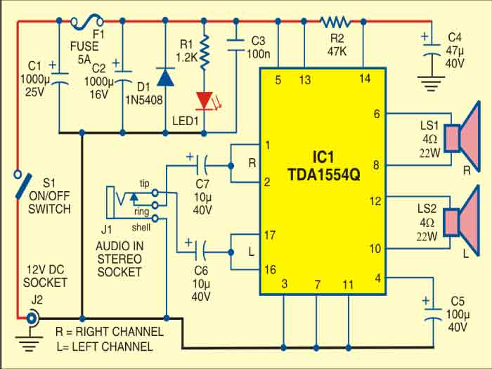
IC TDA1554Q contains four 11W identical amplifiers with differential input stages (two inverting and two non-inverting) and can be used for single-ended or bridge applications. The gain of each amplifier is fixed at 20 dB. Here it is configured as two 22W stereo bridge amplifiers.
The amplifier is powered from the 12V car battery through RCA socket J2. Diode D1 protects against wrong-polarity connection. LED1 indicates the power status.

Connect stereo sound signal from the 3.5mm headset socket of the mobile phone to audio input socket J1. When you play the music from your mobile, IC1 amplifies the input. The output of IC1 is fed to speakers LS1 and LS2 fitted at a suitable place in your car. Electrolytic capacitor C5 connected between pin 4 of IC1 and GND improves the supply-voltage ripple rejection. Components R2 and C4 connected at mute/standby pin (pin 14) of IC1 eliminate the switch on/off plop.
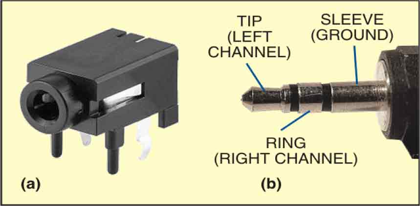
The circuit is quite compact. A good-quality heat-sink assembly is crucial for IC1. Fig. 2 shows the stereo socket and stereo jack.
Construction & testing
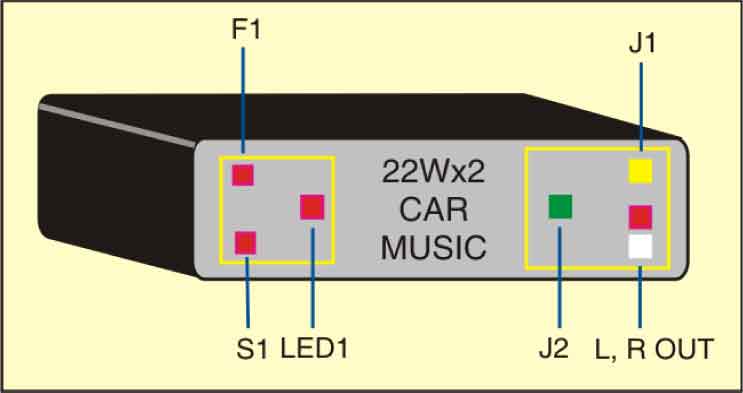
Assemble the circuit on a general purpose PCB and enclose in a suitable cabinet. Small dimensions of the power amplifier make it suitable for being enclosed in a plastic (ABS) case with vent holes. Signal input socket, speaker output terminals, on/off switch, indicator, fuse holder and power supply socket are best located on the front panel of the enclosure as shown in Fig. 3.
The article was first published in October 2010 and has recently been updated.


Where to get kit for the above audio amplifier
Sir, the datasheet link is not working.
404 — File not found.
Hi, the datasheet was removed from the source link. We have removed the datasheet link.