


 Here is a motion sensor system based on PIR motion detector module BS1600 (or BS1700) that can be used for security or corridor lighting in power-saving mode. The 12V DC power supply required for the motion detector and the relay driver is derived from 230V, 50Hz mains using a transformerless circuit as shown below.
Motion sensor circuit

The working of the circuit is simple. When you power-on the circuit after assembling all the components including the CFL, the CFL will glow for 10 seconds, turn off for 30 seconds, glow for 10 seconds and then turn off. Now the circuit is ready to work.
Circuit operation
When any movement is detected, around 3.3V appears on the base of relay-driver transistor T1 and it conducts to energise relay RL1. As a result, Triac1 (BT136) fires to provide full 230V and light up the CFL. Another normally-opened contact of the relay (N/O2) is used here to hold the output until reset. If the switch is not in ‘hold’ position, the light will remain ‘on’ for about ten seconds (as programmed in the motion sensor). In short, when there is a movement near the sensor, the CFL glows for about ten seconds. It will remain ‘on’ if switch S1 is in ‘hold’ position.

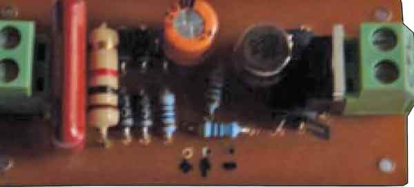
Construction & testing
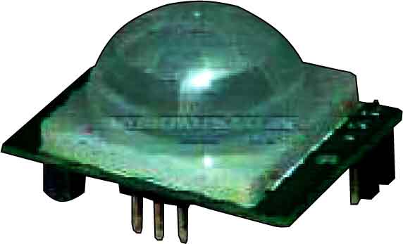
Assemble the circuit on a general purpose PCB and enclose in a suitable cabinet. Use a three-pin connector for connecting the PIR sensor in the circuit with correct polarity. The motion detector is embedded onto the transparent cover of the light assembly as shown in Fig. 2
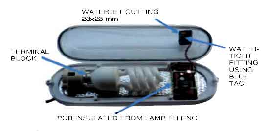
An arrangment of CFL assembly in the author’s prototype (Fig. 3) is shown in Fig. 4. In this arrangement, a PIR sensor and 23W, 230V AC CFL are used. Seal all four sides with Blue Tac for water-tightness. Insulate the track side of the PCB using an insulating foam and glue to the base.
The project was first published in September 2010 and has recently been updated.
sir,
i think relay voltage rating is wrong, cause your using 12V zenar diode it regulates up to 12V as O/P. then how can it handles 5V relay
Here, the relay rating is correct. Firstly, please note that the circuit design is of transformer less design and so the current in the circuit is very very less. Secondly, 12V zener is just for protection and not used as a normal regulator. It protects the circuit from spike or sporadic events. Even if voltage crosses 12V for a short duration, the 5V relay will be able to withstand it.
sir,
im working on your project but here i have to give them a flow chart of this project
n i dont understand how to do this. it will be greatful if u help me. please!
sir, what is the use of zener diode in this circuit?
thank you
The ZENER diode together with R2 are used to reduce the dc voltage to 12V.