 Many projects have been published in EFY on how to program a PC’s parallel port using C, C++ and Visual Basic. Here we attempt the same using MATLAB. The advantage of Matlab is that it does not require any special device driver to run in Windows XP. It has rich ‘help’ documents and a large number of user community on the Internet, including Kluid and Matlab Central, which makes even an absolute beginner create an application quickly.
Described here are two simple application programs in Matlab for controlling eight LEDs and a unipolar stepper motor through the parallel port. Since the files are bulky, you need a PC with at least 512MB RAM to run Matlab.
Parallel port
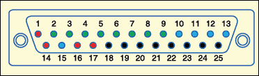
The parallel port of the PC is a 25-pin, D-type connector, commonly known as LPT (line printer terminal) port, having three different ports, namely, data port, control port and status port. Access to the parallel port is via 25-pin, D-type female connector (DB25) as shown below. This female connector is normally available at the back side of your PC.
In order to access any port, you should have its port ID, i.e., the base address of the port. Here the data port has its base address as ‘0378’ in hex format. The addresses of the three ports are in sequential order. So if the address of the data port is ‘0×378,’ the addresses of the status port and the control port will be ‘0×378+1’and ‘0×378+2,’ respectively.
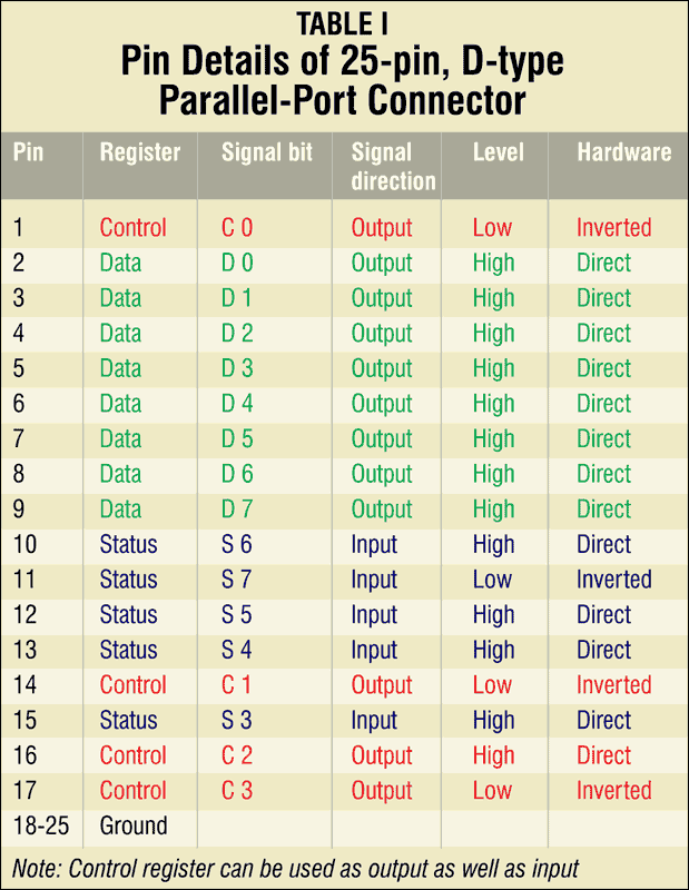
Not all the 25 pins of the port are used for every application. Normally, the eight data lines (pins 2 through 9) along with the signal ground line are used. Pins 2 through 9 form the data port, thus making it an 8-bit wide port. It is a unidirectional port, i.e., it can be used only to output the data to the connected device. Pins 1, 14, 16 and 17 form the control port. It is a bidirectional port, i.e., it can be used both to input and output the data to and from a device. Pins 10 through 13 and 15 form the status port. It is a unidirectional port, i.e., it can be used only for data input from a device. The various pin functions of the parallel port are shown in Table I.

Circuit description
Below is the combined interfacing circuit for controlling the LEDs and the stepper motor through the parallel port. Here, LED1 through LED8 are connected to pins 2 through 9, respectively, of the parallel port. You can check these pins for proper working by clicking ‘all on’ and ‘all off’ buttons from the software (refer Fig.3). All the eight LEDs will glow on clicking ‘all on’ button and turn off on clicking ‘all off’ button. Each individual LED can also be made to glow/turn off by ticking the corresponding checkbox. The LED control application program works without external power supply in the circuit.
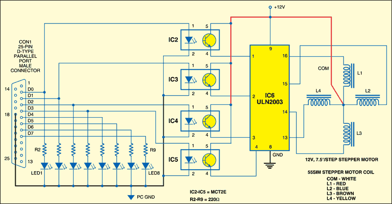

There is another application program used to control the number of rotations, direction (clockwise or anticlockwise) and the rotational speed of the stepper motor. Optocoupler MCT2E ICs (IC2 through IC5) is recommended for interfacing the stepper motor to the parallel port. Each of these ICs has an internal LED and a photo-transistor.

The external circuitry of the internal LED and phototransistor of IC MCT2E differ. The internal LED is driven by the signal from the parallel port, whereas a separate 12V supply powers the photo-transistor. Therefore it completely isolates the parallel port from the rest of the interfacing circuit. This ensures the safety of the parallel port as it can get damaged in case of shorting of the external circuit.
IC ULN2003 (IC6) is used to drive the stepper motor. It is a high-voltage, high-current Darlington transistor array. It consists of seven NPN Darlington pairs that feature high-voltage outputs with internal common-cathode clamp diodes for switching inductive loads. The collector-current rating of a single Darlington pair is 500 mA. The Darlington pairs can be paralleled for higher current capability. Other applications of this IC include relay driver, lamp driver, display driver, line driver and logic buffer.
Stepper motor
Different types of stepper motors with different specifications are available in the market. The one used here is a 55SIM-25DAYG unipolar stepper motor rated at 12V DC, with a step angle of 7.5° per pulse as shown below. This stepper motor has five wires for connection to the circuit. Out of the five wires, four are coming out from the coils of the stepper motor and the fifth is the centre-tapped common terminal.
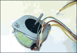
Correct identification and proper connection of these wires are important for successful assembly of the stepper motor. The unipolar stepper motor has two center-tapped coils. Their centre-tapped terminals are joined to make one common terminal. If you have a multimeter, adjust it in the 200-ohm range and check resistances between wires. The resistance between the common terminal and the rest of the coil terminals should be about 36 ohms, while the resistance between any two coil terminals should be about 72 ohms. Connect the coils to the output terminals of the driver circuit in sequence.
To make the project more user-friendly, colour codes of wires for the 55SIM-25DAYG stepper motor are shown in Table II. Note that for the same ratings, different manufacturers may have their own coil specifications.
![355_may-_-table-2-_-efy-]](https://www.electronicsforu.com/wp-contents/uploads/2016/05/355_may-_-table-2-_-efy-.png)
Matlab program
This program consists of 14 M-files and four-figure files. However, only three main programs (parport.m, data_port_controller.m and data.m) have been explained and listed here. Matlab help files are very comprehensive. To get general help, type ‘doc’ command against ‘>>’ prompt in ‘command’ window.
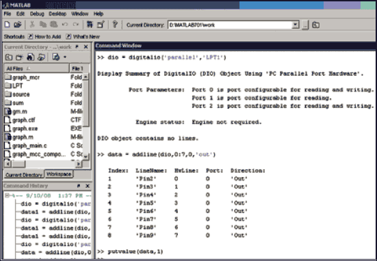
Matlab has a toolbox called DAQ(data acquisition). The ‘dio = digitalio (‘adaptor’, ID)’ creates the digital I/O object (dio) for a specific adaptor and for the hardware device with device identifier ID defined with an integer or a string. The ID can be LPT1, LPT2
The above codes are defined in ‘parport.m’ program as given below:
Matlab comes with a ‘Guide’ tool. Guide (short for ‘graphical user interface design environment’) is similar to Visual Basic (VB) environment. We know that VB is an event-driven programming language which helps users to implement graphics interfaces.
The guide provides a set of tools for creating graphical user interfaces (GUIs). Just type ‘Guide’ against the prompt in Matlab command window. Select ‘Blank GUI’ option in the next window to launch Guide.
Using ‘Layout’ editor option from Guide, you can populate a GUI by clicking and dragging GUI components—such as axes, panels, buttons, text fields, sliders and so on—into the layout area. You can also create menus and context menus for the GUI. From the layout editor, you can resize the GUI, modify and align components, set tab order, view a hierarchical list of the component objects and set other GUI options.
The guide provides controls like push – button, slider, radio button, checkbox, edit text, static text, pop-up menu, list box, toggle-button, table, axes, panel, button group and ActiveX control. It even generates a skeleton M-file (plus figure file with a ‘.fig’ extension) which programmers can further use to link other events through ‘callback’ function. The callback may be an event after a mouse click on a button.
‘callback’ function is used in ‘data_port_controller.m’ program as given below:
![]()
‘checkbox1_Callback( )’ is a callback function executed while you check and uncheck the check boxes corresponding to LED1 through LED8 as shown in Fig.3.
Variables can be used without declaration:
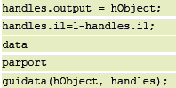
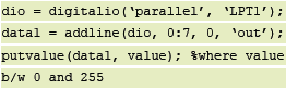
Here, ‘handles.i1’ is a global variable. Every click on the checkbox makes ‘handles.i1’ toggled. ‘data’ is a script file which has only one line of code:
![]()
‘handles.data’ is a global variable which updates a new value and then ‘parport.m’ script file is executed to output the value at the parallel port. Script file executes a sequence of commands rather than accepting or returning parameters. For example, the file generated by Guide is not a script file but a function m-file. Examples of function file include most commands in Matlab, such as sine and plot.
Two more important commands are ‘set’ and ‘get.’ For example, ‘checkbox1’ value sets ‘handles.i1’ as follows:
In ‘stepper_controller.m’ file, the direction control variable returns the toggle state of ‘togglebutton1’ and gives the value to ‘handles.dir’ using ‘get’ command:
Running the program
Install Matlab 7.0.1 software in your computer system. Copy ‘LPT port’ folder from to ‘work’ folder. (It can be found in the files to be download from the link at the bottom of the article.) Click the Matlab icon. Navigate to ‘LPT port’ folder from ‘Current Directory’ section, which is just on top of ‘Command’ window. To run the program, type ‘data_port_controller’ in ‘Command’ window.
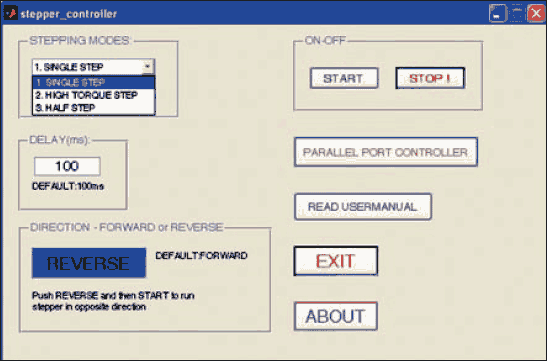
The control of LED has been explained earlier. To control the stepper motor, click ‘Stepper Controller’ button in the program output shown in the circuit. You will get the program output as shown below. Here, you can control the stepper motor in three modes: single-step, high-torque and half-step. Also, the motor can be controlled either in forward or reverse direction. By default, the program is designed to rotate the stepper motor in reverse direction with 100ms delay. You can change these parameters as per your requirement.
Generating standalone program
To run the program without Matlab, create a standalone ‘.exe’ file from ‘M-file’ and port it to other computers using MCR (Matlab component runtime). For that, configure the Matlab compiler as follows: Type ‘mbuild –setup’ against the prompt. Matlab will ask for a few compiler options. Select the default Matlab compiler. Then type ‘mcc–m mfilename.m–o exefilename’. Here ‘mfilename’ must be of function ‘m-file’ and ‘exefilename’ is the filename of the standalone executable file that will be generated. This command generates a few other files along with standalone ‘.exe’ file. Now, you can run the executable file on a PC without Matlab by copying the generated files to that computer.
Construction
Assemble this project on any general purpose PCB or on the PCB shown here in Fig.8 (View as PDF). Component layout for the same is shown in Fig.9 (View as PDF). After mounting all the components on the PCB, fix the 25-pin male connector (CON1) on the PCB as shown in the layout. Use a 9-wire, 50cm FRC cable with 25-pin female connector at one end and male connector at the other end to connect between the board and the PC. Identify the stepper-motor wires and connect the common wire to 12V and the rest of the coils in sequence as shown in the schematic diagram.
Download PCB and component layout PDFs (Fig. 8,9): click here
EFY note
All the relevant files of this project have been included in the link: click here
The project was first published in May 2009 and has recently been updated.