


 An illuminance of 100 to 1000 lux is required for reading and doing close work without eye-strain. Specular illumination or bright sunlight provides 50,000 lux, while twilight or dim light provides only 10 lux. Reading and close work under a fluorescent lamp is better because it can give a flux of 4400 lumens in contrast to 1600 lumens of a tungsten lamp. If the eyes are exposed to dim light for many hours, dark adaptation will develop and there will be severe eyestrain. Here is a circuit for light intensity measurement. It can give a visible linear scale of illuminance in a comparative form of different light levels such as minimum, moderate and maximum.
Circuit for light intensity measurement
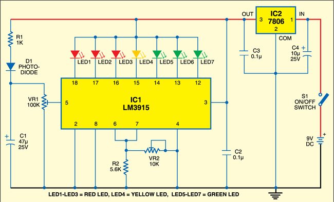
The circuit uses a p-n photodiode as the light sensor and a display driver IC LM3915 (IC1) to give a logarithmic current scale linearly with the incident light energy. The photodiode has a high-frequency response and fast switching speed of one nanosecond compared to cadmium-sulphide (CdS) photodetectors. The ‘n’ material of the photodiode is composed of pure silicon doped with phosphor to give free electrons. The ‘p’ material is formed of pure silicon with boron as the doping material. It provides free holes.
Circuit operation
In dark, reverse saturation current develops in the photodiode and free electrons move when it gets light. The linearity of light current generation in the photodiode is proportional to irradiance. Typically, the light current is 10 to 90 µA at 5 volts and the radiation sensitivity of a p-n photodiode is 0.4 to 4 µA/mW/cm2.
In the circuit, the photodiode is connected in forward-biased mode through current-limiting resistor R1 to get the light current. The current generated by the photodiode in response to light passes to input pin 5 of IC1 through preset VR1.
IC LM3915 has a complete built-in voltmeter circuit to indicate varying input voltage directly on the LED scale. Each LED from pin 18 downwards lights up when input pin 5 of IC1 receives an increment of 1.25 volts. Internally, the IC has ten comparators with a current source output, plus a reference and ladder voltage divider that provides the necessary reference voltage. Pin 7 of the IC is maintained at a reference voltage of 1.25 volts and resistor R2 controls current through the LEDs and thus their brightness.
By varying preset VR2 you can set the lower limit of the light intensity at which the first LED (LED1) should light up. By varying preset VR1 you can set the input voltage to the IC for the upper limit at which LED7 should light up. LED1 indicates minimum light, LED4 (yellow) indicates moderate light and LED7 indicates normal light. Capacitor C1 provides a slight lag to turn on/off each of the LEDs.
Construction & testing
Assemble the circuit on a general-purpose PCB and enclose in a suitable cabinet. When adjusting VR1, the wiper of VR2 should be fully turned in the clockwise direction.
EFY note
The circuit will not work in fluorescent lighting, as it is pseudo light without monochromatic spectrum.
The article was first published in August 2009 and has recently been updated.
How can I simulate this in any simulation software such as multisim . Can anyone help me with this