RGB LEDs are capable of generating a variety of colours by mixing red, green and blue colours. It is sometimes very interesting to replace single-colour LEDs and produce different colour combinations from these three basic colours using RGB LEDs. Usually, RGB LEDs have four pins—one for each colour and a common cathode.
Circuit Explaination
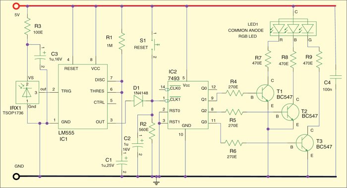
Presented here is a simple application of RGB LEDs that produce different combinations of colours every time these are triggered by some IR remote control. The circuit is built around the 4-bit binary ripple counter 74HCT93 (IC2), timer IC TLC555 (IC1), photo module TSOP1736 (IrX1) and some discrete components.
74HCT93 (IC2) internally consists of four master-slave flip-flops that form a divide-by-two and divide-by-eight sections. Each section has a separate clock input (pin 14 and pin 1) to initiate state changes of the counter on the high-to-low clock transition. Outputs (Q1 through Q2) of IC3 are connected to the base of independent transistors (T1 through T3). The R, B and G terminals of the RGB LED are connected to the collector of transistors T1, T2 and T3, respectively, through 470-ohm current-limiting resistors.
As soon as the output from IC3 becomes active, it turns on the corresponding driver transistor (T1 through T3) and the current starts to flow through the respective LEDs inside the RGB LED. IrX1 (TSOP1736) is an integrated infrared receiver. The CMOS timer chip TLC 555 (IC1) here is wired as a mono-stable multivibrator.

The circuit can be controlled with the help of an infrared remote control. Any commonly available TV/video/audio appliance remote control handset can be used for the purpose. Just press any key of the remote control to change the RGB LED’s display mode to next level. Manual control is also possible through a push-to-on switch (S1), attached to pin 1 of IC2.
Working of the circuit is simple and straight-forward. Whenever a high-to-low transition occurs at the clock input (pin 1) of IC2, digital value at the output of its counter increases and a different LED (or a colour combination) lights up to produce a different colour output. This action repeats with each input trigger (as a result of the remote control or push switch activity), and after the highest value the counter starts from the beginning again. This way all colour combinations will have their time and, as long as the circuit remains powered, IC2 will recall its last counter value and hence the corresponding colour mode of the RGB LED.
A simple regulated power supply based on the standard 7805 voltage regulator is required for standalone use. This regulator circuit can then be used to power the whole circuit from a 9V-12V power adaptor or another DC power source.
Assemble the circuit on a general-purpose PCB and enclose in a small plastic cabinet, making sure that the infrared receiver (IRX1) sticks out. Add a suitable LED reflector and re-tune the value of R7 through R9 to get the best visual effect from the RGB LED used in your circuit.


Can IR receiver directly be used with clock pin (pin 1 of 7493 IC)?