
 Semiconductor relays provide the same function as electromechanical relays but have no moving parts, which increases their long-term reliability. These relays provide an array of solutions, meeting the needs of today’s high-performance applications.
Presented here is the design of such a relay for automotive applications that uses two series connected MOSFETs to achieve bidirectional conduction with advantages like:
- No mechanical moving parts
- No arching in contacts
- No acoustical noise
- No EMI from contacts commutation
- High switching speed
- High reliability
- Long operating life
- Resistance to shock and vibration
Circuit and working
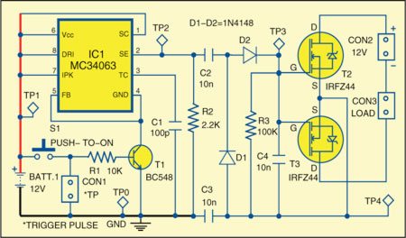
Fig. 1 shows the circuit of semiconductor relay for automotive applications. The circuit is built around switching regulator MC34063 (IC1) and a few discrete components. IC1 acts as an astable multivibrator, producing high-frequency square wave. This square wave is fed into a simple rectifier.Capacitors C2 and C3 help to achieve electrical isolation between the control circuit and the load.
Download PCB and component layout PDFs:click here
Applying a trigger pulse to the base of T1 allows oscillator IC1 to function. On the floatingside, the combination of diodes D1 and D2, and capacitor C4 gives biasing voltage to MOSFETs T2 and T3. Removing the control signal switches off T2 and T3. Resistor R3 provides a discharge path for C4, allowing the MOSFETs to switch off in approximately 3 milliseconds. For faster turn-off, you can reduce the value of either C4 or R3 at the expense of increased ripple on the rectified gate voltage.
When the MOSFETs are off, their parasitic diodes connect in series opposition and thus block conduction. You can select from a range of MOSFETs to match your application’s requirements, but make sure that the voltage you apply to the gates of T2 and T3 is sufficientto fully switch both the devices into full conduction.

Construction and testing
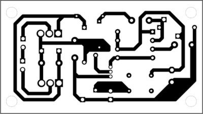
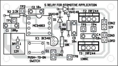
An actual-size, single-side PCB for the semiconductor relay for automotive applications is shown in Fig. 2 and its component layout in Fig. 3. After assembling the circuit on a PCB, enclose it in a suitable case.
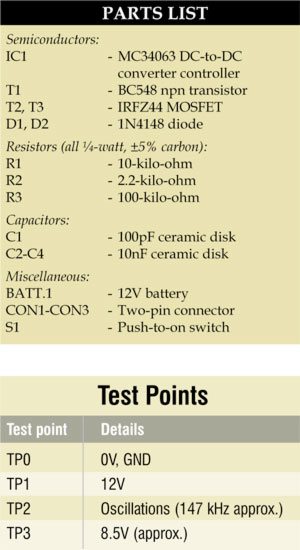
To test the circuit for proper functioning, verify 12V DC at test point TP1 with respect to TP0. Now press switch S1 and verify oscillations at TP2. Also check biasing voltage at TP3 with respect to TP4 as mentioned in the table. Please note that switch S1 is provided for testing purpose only. CON1 should be used for external trigger.

The author is managing director of Quantum Dots Technology Pvt Ltd, Chennai, and a regular contributor to EFY

Why do you need 2 output devices?