


 This square root generator circuit generates the square root of the input at a reference voltage. Such type of square-root output is normally used in R&D labs.
Square root generator circuit
Shown below is the proposed circuit. A sawtooth wave is generated by charging a capacitor at a specified rate and then rapidly discharging it through a switch. Let us assume that initially, capacitor C1 is completely discharged and hence the voltage at the output terminal of op-amp LM356 (IC1) is zero. Since the non-inverting terminal of op-amp IC1 is grounded, the current through resistor R1 (Vr/R1 amps) charges capacitor C1.
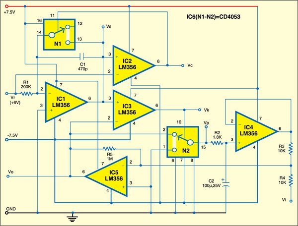
As the output of IC1 reaches the reference voltage level (Vr=6V), the output of op-amp IC2, configured to work as a comparator, goes low to open switch N1 built around IC6 (CD4053). When the output of IC1 crosses Vr level, say, after time period T, the output of comparator IC2 goes high. Switch N1 closes to short capacitor C1 and hence Vs drops to zero.

During time period T,
Vs= (Vr/ (R1xC1) ) t ---------- ( 1)
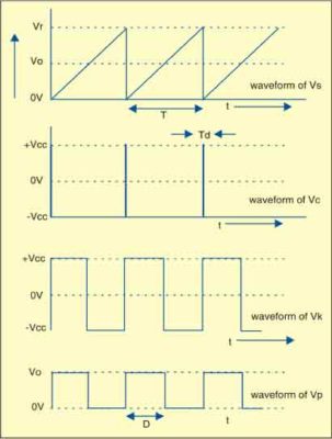
After a very short delay time (Td) required for capacitor C1 to discharge completely, the output of comparator IC2 becomes low and switch N1 opens, allowing C1 to resume charging. Thus this cycle repeats after time T+Td. The waveforms of voltages available at Vs, Vc, Vk and Vp points are shown below.
When time t = T and Vs=Vr, from Eq. (1) we get
T = R1xC1 ——– (2)
As shown in Fig. 1, comparator IC3 compares the sawtooth waveform at its pin 3 with output voltage Vo and outputs a pulse train at pin 6.
Output voltage Vo is proportional to the square root of input voltage Vi as follows:
Vo = √Vi Vr
The circuit works off +_7.5V DC. Switches N1 and N2 are realised using IC CD4053 (IC6).
Construction & testing
Assemble the circuit on a general-purpose PCB and enclose in a suitable cabinet. Connect three terminals for positive, negative and ground of the power supply on the rear side of the cabinet, and three terminals for input, output and reference on the front panel.
The project was first published in May 2011 and has recently been updated.
