
 LDR-based automatic lights flicker due to the change in light intensity at dawn and dusk. So compact fluorescent lamps (CFLs) are unsuitable in such circuits as flickering may damage the electronic circuits within these lamps. The sunset lamp circuit described here can solve the problem and switch on the lamp instantly when the light intensity decreases below a preset level.
Sunset Lamp circuit description
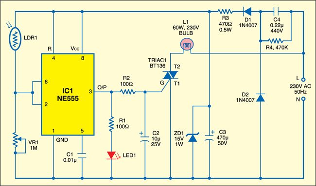
This sunset lamp circuit uses popular timer IC NE555 (IC1) as a Schmitt trigger to give the bistable action. The set and reset functions of the comparators within the NE555 are used to give the instantaneous action. The upper threshold comparator of IC1 trips at 2/3Vcc, while the lower trigger comparator trips at 1/3Vcc. The inputs of both the threshold comparator and the trigger comparator of NE555 (pins 6 and 2) are tied together and connected to the voltage divider formed by LDR1 and VR1. The voltage across LDR1 depends on the light intensity.
In daylight, LDR1 has low resistance and the input voltage to the threshold comparator goes above 2/3Vcc and its output becomes zero, which resets the internal flip-flop of IC1. But the input to the trigger comparator is still more than 1/3Vcc, which keeps output pin 3 of IC1 low. Triac BT136 connected to output pin 3 of IC1 remains quiescent due to insufficient value of current for firing it. Thus lamp L1 remains ‘off’ during daytime.
Circuit operation
At sunset, the resistance of LDR1 increases, and the voltage at the input of the threshold comparator decreases below 2/3Vcc and that of the trigger comparator goes below 1/3Vcc. As a result, the outputs of threshold and trigger comparators go high, which sets the flip-flop. This changes output pin 3 of IC1 from low to high. Triac1 gets the necessary gate current through resistor R2 and fires. Thus it completes the power supply to the lamp through Triac1. LED1 glows to indicate the high output state of IC1.
Power supply to the circuit is directly derived from the mains through capacitor C4. This capacitor delivers current in the circuit. Diodes D1 and D2 rectify the AC from capacitor C4 and capacitor C3 provides the necessary smoothing. Zener diode ZD1 provides rectified 15V DC for the circuit. Bleeder resistor R4 removes the stored voltage of the capacitor when the circuit is unplugged.

Assemble the circuit on any general-purpose PCB and enclose in a plug-in type adaptor box. Connect the live and neutral points to the pins of the adaptor box. Provide in the box 5mm holes for LDR1 and LED1. Plug the unit at a place where daylight is sufficient to inhibit the circuit operation during daytime. Light from the lamp should not fall on LDR1 at night.
Caution: The circuit carries 230V AC and most of its points are at mains lethal potential. So do not touch any point in the circuit when it is powered and adjust the preset only with a plastic or insulated screwdriver.
The project kit is available at grab.electronicsforu.com.

More interesting projects available here.

.22micro,440v capacitor doesn’t available in the market is any another component can I use in that place
Have you tried this circuit? Is it work?
Yes, similar polyester capacitor with about 440V rating can be used.
.22micro,440v capacitor doesn’t available in the market. can i use .22micro,275v