
 This intercom circuit based on IC LM380 audio amplifier requires very few external components. So the circuit is very easy to assemble.
Intercom circuit
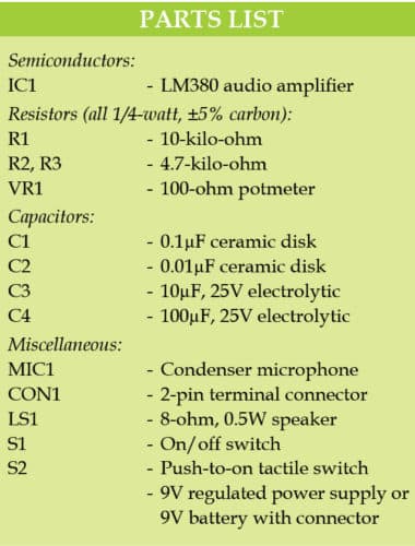
Circuit diagram of the intercom is shown in Fig. 1. In addition to audio amplifier LM380 (IC1), it uses a condenser microphone (MIC1), an 8-ohm, 0.5W speaker and a few other components.
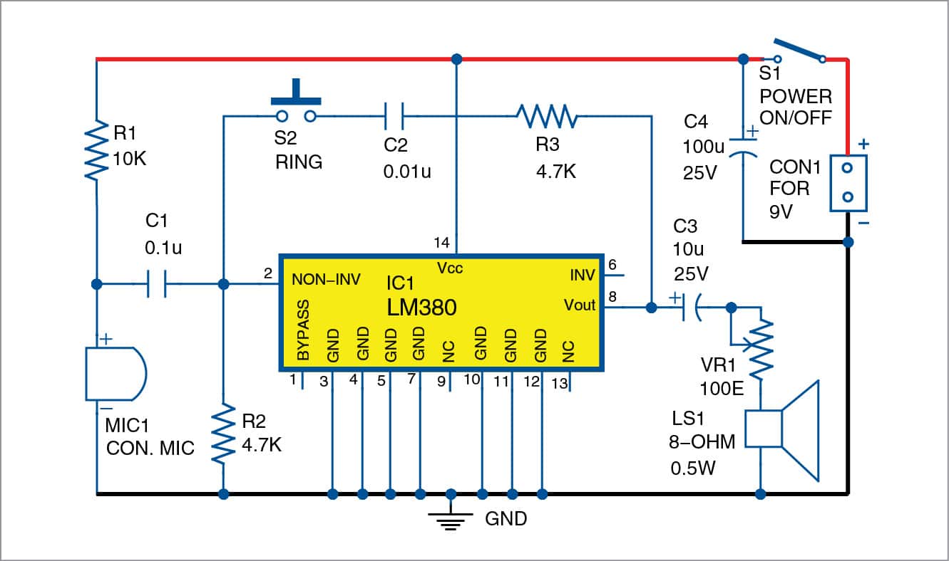
Assemble the same circuit on two separate units. In order to use these units as intercom, extend the output (LS1) of the first unit to the second unit placed in a remote location and vice versa. Set the required sound level by adjusting potmeter VR1. Press switch S2 momentarily to generate an audio tone in the speaker (LS1).
The circuit works off a 9V DC battery. Alternatively, you can also use a 9V unregulated power supply.
Construction and testing
A PCB layout for the intercom is shown in Fig. 2 and its components layout in Fig. 3.

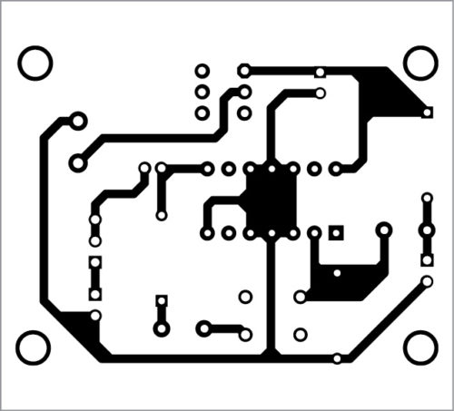
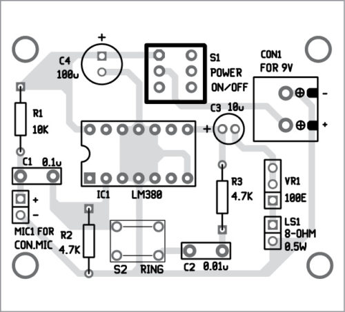
Download PCB and component layout PDFs: click here
To test the circuit, you need two units of the same circuit. Extend LS1 from the first unit to the second unit, and LS2 (not shown here) from the second unit to the first unit.
To talk over the intercom, press switch S2 to ring up the person sitting on the remote side where the second unit is placed. Then you can speak into microphone MIC1. The person at the other end should be able to hear you through LS1. Similarly, when he rings you up, you should be able to hear him through LS2.

Use shielded wires for connections to both the units.


Can we use lm386 instead of lm380 as a audio amplifier
Both the ICs( LM386 and LM380 )are audio amplifier but they are not pin to pin compatible.
Hey, how do you connect both circuits? Like at what circuit place I need to connect it? Can you make picture how to connect LS1 and LS2
Assemble two same circuits, say Circuit1 and circuit2. Assuming that you are in first room1 and your friend is in second room2. Place Circuit1 in room1, and Circuit2 in room2. Take a pair of wire upto 5 meter long, connect this wire to LS1 and the circuit1. Place LS1 in room2. Similarly, take another pair of wire with 5 meter long. Connect the wire between LS2 and Circuit2. Place LS2 in room1. Now, you can start talking to your friend.
10uF 25v capacitor is not available in market
And this circuit is not working
10uF capacitor is not very critical. You can replace it with any of its nearby equivalent value example: 22uF, 33uF, 47uF or even 100uF. Please check proper connections as per the circuit diagram given here and also check the sound level control VR1.
I needed to connect 4 stations simultaneously. How can I do it
Not able to produce sound in above circuit