 This unique ultrasonic burglar alarm makes use of the invisible, inaudible ultrasonic sound beam to detect movements. Ultrasonic transducers operate at maximum efficiency when driven at 40kHz frequency. So an ultrasonic transmitter and receiver pair operating at 40 kHz is used to control the buzzer or the relay.
Ultrasonic burglar alarm
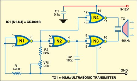
The transmitter unit is built around CMOS IC CD4001 (see Fig. 1). By adjusting the 22-kilo-ohm preset (VR1), the oscillator frequency can be set to approximately 40 kHz. The ultrasonic transmitter transducer is driven by two complementary buffer stages of CD4001 and its current drain is very low.

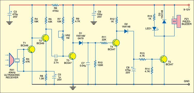
The receiver unit uses a two-stage 40kHz preamplifier followed by switching circuit, buzzer driver, etc (see Fig. 2). Adjust VR2 in the receiver circuit till the buzzer stops sounding while the receiver senses ultrasonic sound from the transmitter.

When the ultrasonic beam is interrupted by the movement of a person or any other object crossing its path, npn transistor T4 stops conducting and transistor T5 conducts. It activates the buzzer and LED1 for three to four seconds. This duration depends on the time taken by 470µF capacitor (C8) connected at the base of transistor T5 to discharge fully through resistor R13. The burglar alarm duration can be set to a desired value with the values of C8 and R13.
Construction & testing
The alarm circuit comprising transmitter, receiver and associated circuits operates off a 9-12V regulated power supply. The receiver circuit requires regulated 12V. You can also use unregulated power supply here.
Assemble the transmitter and receiver circuits on separate general purpose PCBs. Align the ultrasonic transducer such that the signal falls directly on the ultrasonic receiver. The piezobuzzer (PZ1) can be replaced with a relay to control the mains operated alarm.
The article was first published in April 2008 and has recently been updated.


