


Electrochemical processes taking place in our body generate complex signals (hum) that are continuously being passed along the nerve fibres throughout the body. Any physical activity such as muscle movement increases hum. Here’s an auto reset proximity detector circuit that operates when it detects hum generated by the human body in proximity.
Its versatility lies in the fact that you don’t need to touch the metal plates for detection. Just the presence of your hand/body within 1 cm of the sensing loop triggers the circuit. The activation of the circuit is indicated by the glowing of an LED and an audible beep. The circuit continues to glow and beep until the hand is within 5 cm of the loop. Beyond 5 cm, it resets automatically.
Auto Reset Proximity Detector Circuit
Here IC2 (555) simplifies the circuitry otherwise needed to achieve this. Regulator 7809 (IC1) supplies 9V DC to the circuit.

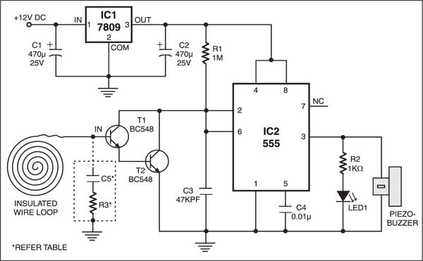
When power is turned on, capacitor C3 (47 kpF) charges through resistor R1 (1 mega-ohm). Output pin 3 of IC2 remains high as long as the voltage at its pin 2 is below 2/3Vcc; the buzzer beeps for this period. Beyond that voltage, the output resets (goes low).
Transistors T1 and T2 (each BC548) form a Darlington pair. As long as T1 and T2 remain in cut-off condition, capacitor C3 retains the charge and the buzzer is off. When you take your hand within 1 cm of the loop wire, T1 conducts due to the noise picked up by its base. So capacitor C3 gets a discharge path, and the voltage at pin 2 of IC2 going below 1/3Vcc sets output pin 3 high. As a result, the buzzer sounds.
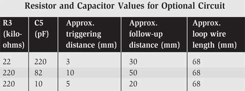
The beep continues until C3 charges to 2/3Vcc due to gradual withdrawal of the hand from vicinity of the loop wire. The series combination of capacitor C5 and resistor R3 within dotted lines is optional and reduces hum at the base of T1. The values of C5 and R3 to be used for varying the sensitivity of the circuit are given in the table.
Construction & testing
For calibration, wire the circuit and use a 7 cm hook-up wire at the base of T1. When you place your hand over the wire insulation, the buzzer should beep. If it doesn’t, check connections. Now connect the loop wire. If beep continues even when there is no person within 20 cm, use a suitable combination of C5 and R3 from the table to reduce the circuit sensitivity.
The suggested PCB size for the circuit (excluding power supply) is 4 cm×3 cm. Solder the loop wire directly. A small hook-up wire was used in the prototype.
Do not remove insulation of the wire. Keep the circuit away from mains wiring and large metal objects.
The article was first published in January 2004 and has recently been updated.
is projectt sy related koi video hy tu plz share kr dein
How make pinpointer?