
 A water pump controller senses the level of water in a tank and drives the water pump. The circuit described here is built around timer IC1 (555). When the water level of the tank goes below the low level marked by ‘L’ the voltage at pin 2 of IC1 becomes low. As a result, internal SR-flip-flop of IC1 resets and its output goes high. This high output pin 3 of IC1 drives relay driver transistor T1 (BC547) and energises relay RL1. Water pump gets mains power supply through n/o contacts of the relay and is powered on. It starts filling water in the tank.
Water pump controller circuit
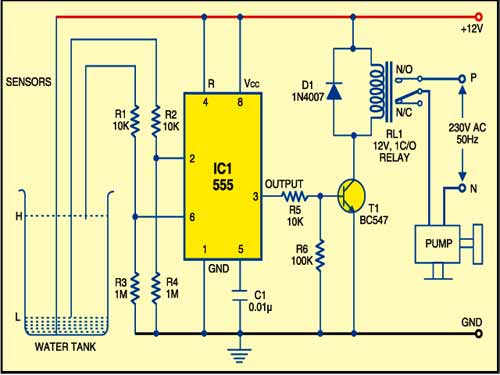
When the water level goes high and reaches the high level marked by ‘H’, the voltage at pin 6 of IC1 also goes high. As a result, internal SR-flip-flop of IC1 sets and its output goes low. This low output pin 3 of IC1 cuts off relay driver transistor T1 and de-energises relay RL1. Water pump disconnects from the mains power supply through n/c contacts of the relay and goes off. This stops the water flow.
Construction & testing
Use 12V battery or 12V adaptor to operate the circuit. Assemble the circuit on a general-purpose PCB and enclose in a suitable cabinet. Use three-sensor (thick conductive wire) and fit into the tank ensuring that 12V sensor touches the bottom and low-level sensor remains just above the bottom. The high-level sensor should be placed at a height till where the water needs to be filled. The circuit is economical, highly reliable and can be easily constructed.
The project was first published in January 2010 and has recently been updated.


Can i use it for dewatering by reversing high and low sensor? I want to start pump when tank level reaches high level and stop at low level?
The author Suresh Kumar K. B. replies: Easiest way is to connect pump input phase (P) to N/C
can you share the prototype of this circuit
Dear Sir,
Instead of AC power supply and Pump, Can we use 9V DC and Toy Pump? Will the circuit work?
Yes it works
Sir if i use 3volt motorinstead of water pump and 6 volt supply and 6 volt relay…. Will it work?
yes 555 voltage range is 5-15 v
Sir for the above-mentioned ckt how much maximum load that means HP motor can be connected
If in case of over load r long term running process relay damage r by over heating if it melts internally short ckt there is a chance of ac current pass through water tank if it is means very dangerous
Pls reply me
I have a 12V pump running from a solar panel to fill a horse trough. I want to turn the pump off when the trough is full. The pump is down a well which should not run dry. Problem the trough is 35 yards from the panel and 50 yards from the pump. Can anyone suggest how to run this I’m assuming the voltage drop over that distance will defeat 12V if I just put a float switch in the tank and run the pump circuit through it.
Regards