
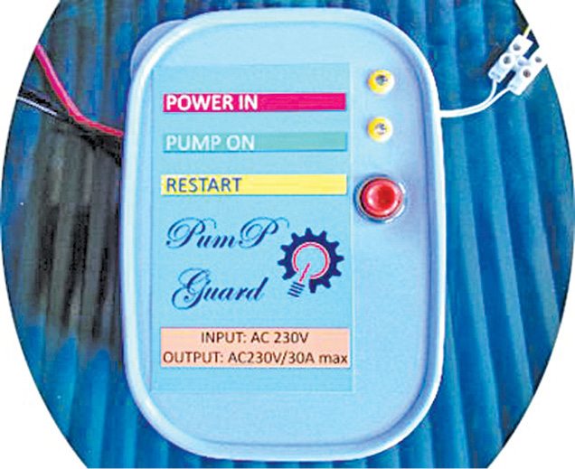
 Presented here is a water pump dry run guard that works as an effective solution for protection of household submersible water pumps against dry running. Minimum water-level monitoring feature in the circuit is realized using suspended sensor probes to ensure that the water pumps will not run under a dry condition. Besides, switch-on and return-delay features prevent the pumps from unwanted brief operation when handling turbulent underground water. Fig. 1 shows the author’s prototype.
Circuit and working
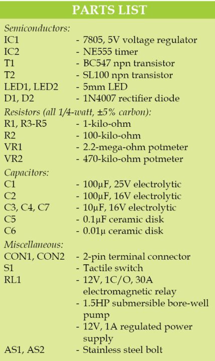
Circuit diagram of the water pump dry-run guard is shown in Fig. 2. It is built around 5V regulator 7805 (IC1), timer NE555 (IC2), transistors BC547 (T1) and SL100 (T2), a 12V 1C/O relay (RL1) and a few other components.
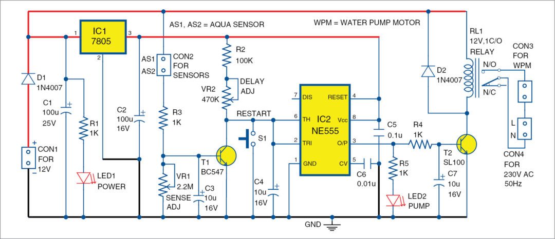
To understand how this circuit works, assume that output pin 3 of IC2 is high during initial power up and, hence, the relay RL1 is in energised state. In this case, capacitor C4 at the input of IC2 will be charged via resistor R2 and potmeter VR2.
After a few seconds delay, voltage on C4 will reach a level that causes the inverter circuit (formed by IC2) to change state. IC2 output will flip to low level, and RL1 will be switched off by relay-driver transistor T2. Push-to-on restart switch S1 can be used for actuating this process from the beginning.
However, if presence of water is sensed by aqua-sensor probes (or water-level sensors) AS1 and AS2, C4 will be discharged endlessly by T1 to hold RL1 in its energised state. But, when a dry-run condition occurs (where no moisture is detected by AS1 and AS2), the inverter changes its state after a short delay (10 to 13 seconds). The time interval (delay) between state changes depends mainly on the setting of delay-adjustable preset pot VR2.

A 12V, 1A DC supply from any transformer based or SMPS power supply can be used for powering the entire circuit. Note that, in order to increase system stability, an onboard 5V regulated DC power supply is used here. The 5V DC regulator circuitry is realised using IC1, C1 and C2. Besides, VR1 is included in the aqua-sensor circuitry because distance between the master circuit and sensor probes may be rather large, so it can compensate for possible cable resistance.
Two closely-spaced (about 10mm apart) stainless-steel bolts may be used as aqua-sensor probes. For the interconnection, use any low-voltage twin-wire/cable with a length of 30 to 90 metres.
LED1 is the power-on indicator while LED2 functions as the motor-on indicator. Since output load is a power-hungry water-pump motor, a 12V DC power relay with AC 230V/30A switching capacity is highly recommended for flexible and reliable operation. Power supply to the output load must be routed through the common pole and N/O contact of this power relay.

Construction and testing
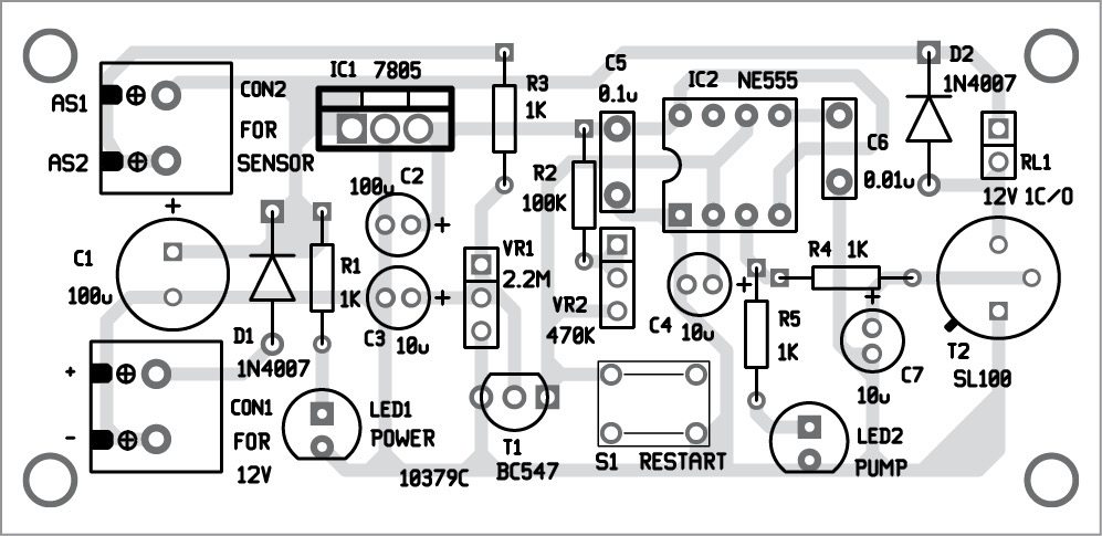
An actual-size, single-side PCB layout for the water pump dry-run guard is shown in Fig. 3 and its components layout in Fig. 4.
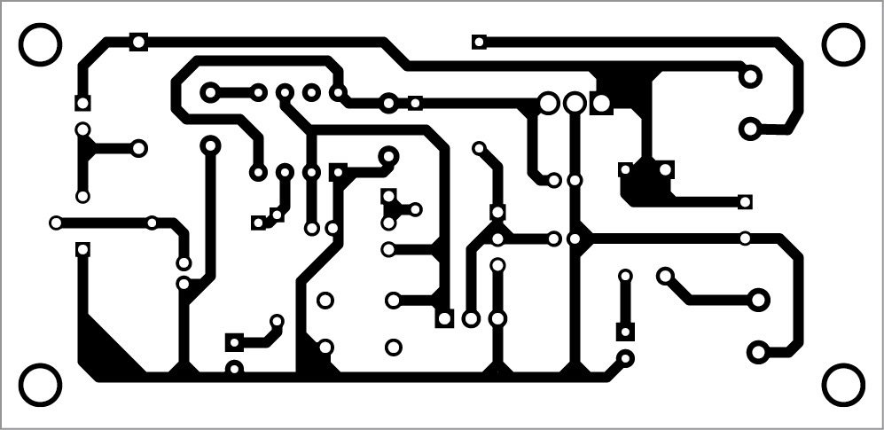
Download PCB and component layout PDFs: click here
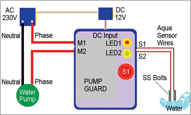
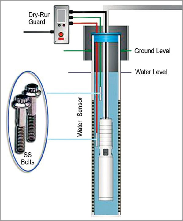
After assembling the circuit on the PCB, connect the whole system as shown in the electrical wiring diagram in Fig. 5. System overview with a submersible bore-well pump is shown in Fig. 6. Connect the water-pump motor across CON3 and 230V AC mains across CON4.
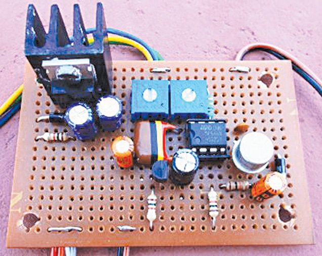
The circuit can also be fabricated on a medium-size perfboard. For mechanical reasons and to simplify construction, the electromagnetic relay should be kept at a distance from the circuit board. After successful construction and initial testing, enclose the whole system in a rigid plastic/metal container.
Note that the prototype was tested with a 12V/100-ohm (AC 230V/30A DPDT) power relay. Power supply used was a 12V/1A linear power supply. Output load was a 1.5HP submersible bore-well pump. Test value of VR2 was 0-ohm (at 10 seconds delay), and value of VR1 was 500-kilo-ohm. Wire length of the aqua-sensor probes was around 30 metres.
[stextbox id=”warning” caption=”Caution:”]Shock hazard! Construction and connection of this circuit should only be carried out by qualified personnel, and all electrical safety regulations must be observed. In particular, it is essential to ensure that the relay chosen is appropriate for use with powerful water pumps, and is suitably rated to carry the required voltage and current.[/stextbox]


great circuit ,thanks will use
You are most welcome.
How to Make Water Sensor.
i want to use buzzer instead of relay how to connect and what are the changes to be made thank you
I am looking for this readymade designed PCB layout circuit and components. Can you please let me know the availability and address from where the same can be bought
Hi,
Thanks for the circuit.
Please let me know you have circuit for mono-block pump with dry run protection. Please send to my email.
Regards.
Hello. I made this device and it works perfectly. I’m interested in whether and how this device can be upgraded. When the motor shuts down due to water loss, it automatically resets itself after a certain time. For example, the trimmer can be set to 1-30 minutes.
Thanks in advance.