Whiskers for robots are simple switch-type sensors that work like an animal’s whiskers detecting nearby objects in the environment. When disturbed, the sensor sends a pulse to the robot to indicate that an obstacle is present.
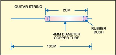
Sensitive but inexpensive general-purpose whiskers can be made using commonly available steel guitar strings. These strings are very flexible, conductive and easy to use. Take a 2cm long, 4mm dia. copper tube. Cut a length of guitar string (10 cm is enough) and slide the string into the copper tube. Fix the string centrally within the tube using a suitable rubber bush insert at the end of the tube. The final mechanical whisker should look as shown in Fig. 1. Solder a wire to one end of the copper tube and solder another wire to the end of the steel string.
An electronic circuit shown in Fig. 2 is added to the whisker switch shown in Fig. 1. The schematic is shown for only one of the four channels that can be made with one LM339 (IC1). IC LM339 series consists of four independent precision voltage comparators with an offset voltage specification as low as 2 mV max for all the four comparators. These are designed specifically to operate from a single power supply over a wide range of voltages. We have used only the first comparator here.
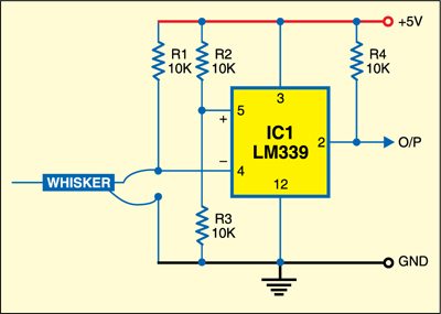
The non-inverting input (pin 5) of IC LM339 is connected to a fixed voltage through divider network resistors R2 and R3. The inverting input (pin 4) is pulled high through R1 and connected to the mechanical whisker as shown in Fig. 2. Pull-up resistor R4 is used because the LM339 has only open-collector outputs. The working is simple. Initially, when there is no interruption, the output of the comparator remains low. As and when any obstacle disturbs the guitar string of the whisker switch, pin 4 of IC1 goes low and output pin 2 of the first comparator of IC1 becomes high momentarily. We have described only one comparator but you can use the other three comparators similarly. The brain (microcontroller) of the robot can now read the status of the whisker switch through this comparator output.
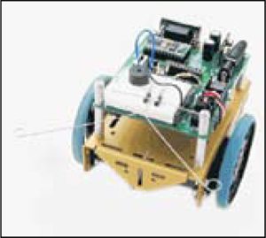
Assemble the circuit on a small general-purpose PCB and connect all the four whiskers to your micro-controller-based robot as shown in Fig. 3.